Forming
We understand the importance of ongoing investment in the latest technologies, equipment and training to the high standard of our output quality and IATF 16949 certification. Our programme of continuous improvement means that our metal bending and folding capacity can meet the most demanding metal fabrication contracts, large or small, simple or complex.
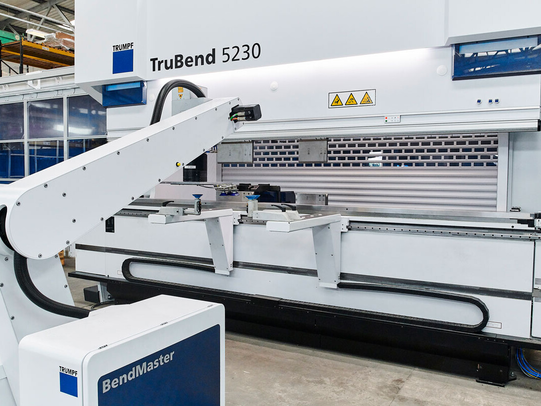
Newfield’s modern metal fabrication facility includes 10 press brakes and a new, fully automated bending machine. It is comprised of a 230T press, 150kg bendmaster and ToolMaster. The cell can produce unmanned parts weighing in excess of 100kg and complete changeovers for multiple product runs. It also uses the ACB system, which monitors and corrects forming during manufacture to remove the need for rework.
Our extensive press brake forming capacity includes Trumpf, Amada and Bystronic machines, with a press range from 50 to 400 tonnes. Press brakes can often handle a broader range of material thicknesses than panel benders, allowing us to maintain versatility within the market.
The use of semi-automated measurement systems reduces manufacture processing time, improving site efficiency. This is also supported with offline programming to minimise downtime on new product introductions.
The process is ideally suited to both volume production and parts that are difficult to handle, heavy or complex. The aim of robotic bending is to improve accuracy through ACB technology, reducing the safety risks associated with manually forming heavier parts and reducing cost through increased productivity.
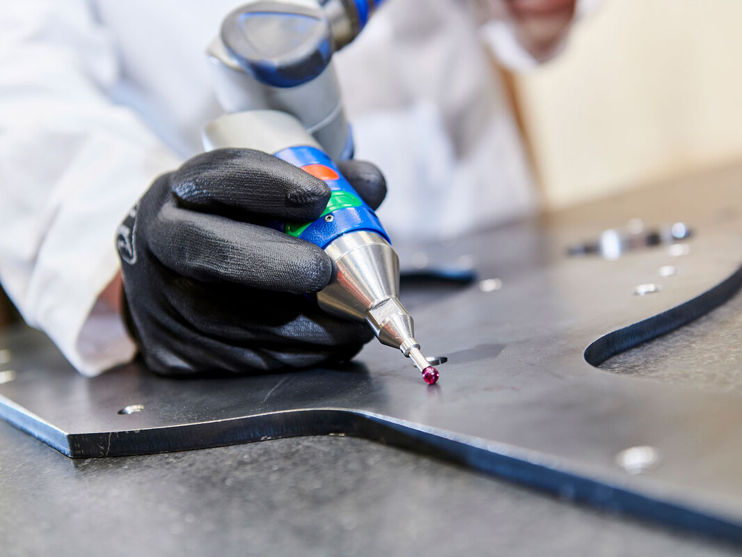
Our robotic forming cell is comprised of a Trumpf bending cell – a TruBend 230S. It offers automated tool selection, material loading and a conveyor system for flexible storage. It enables us to perform ‘lights-out’ operations, where the machine is programmed and loaded before being left to run autonomously. Its built-in checks are verified by our engineers using a measurement system analysis (MSA) process.
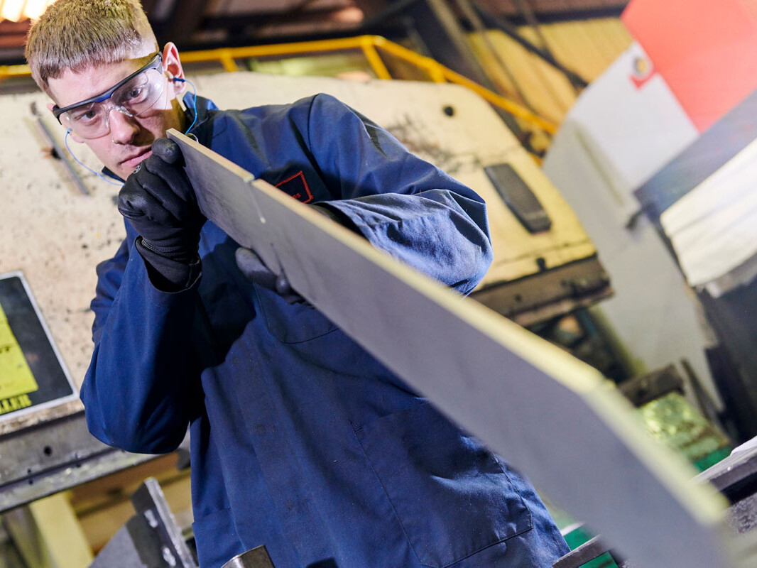
Metal folding is used to create many products including pipes, enclosures, boxes and more, as sheet metal can be fashioned and reshaped in many ways such as rolling, indenting, bending and shearing.
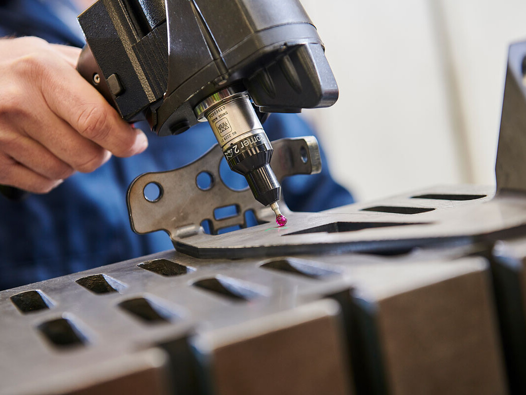
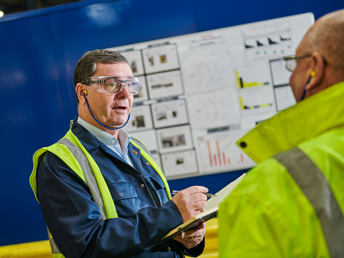
Newfield’s quality assurance team carry out in-process checks throughout fabrication to ensure repeatable high accuracy, whilst advanced 3D measurement technology guarantees all components meet the very tight tolerances required by our customers.
Automated forming
Greatly improved efficiency and consistent output.
Newfield’s new TruBend Cell 5000 provides productive and flexible automation for a wide range of products, producing them to a consistently high standard. It is capable of producing parts up to 100kg with very precise angles. It is also incredibly efficient and reduces production time while maintaining reliable output and material handling.
Programming
Investment in software and the establishment of SOPs guarantee Newfield’s quality forming.
Using the latest software, our Engineering team are able to design the parts as well as create Standard Operating Procedures (SOPs) to show the operators how to complete each operation. We have also adapted this software for use on our non-automated machines, making tool selection easier and improving accuracy. These SOPs are included in information packs that accompany each part around the factory.
Learn more about our design considerations for bending work.
More Information
Here at Newfield, we utilise a process known as ‘air bending’ that uses the minimum amount of force possible. This maximises the capability of the press brake while reducing tooling wear.
Bend Radius (Inside Bend Radius)
With air bending, the inside radius is predominantly determined by the die opening (also referred to as V-width). In order to reduce the required force, a larger V-width must be used. Generally, the minimum inside radius is equivalent to the thickness of the material. Because dies are manufactured in specific sizes, generous tolerances should be allowed – up to ± 30%.
Minimum Flange Length
It is recommended that the minimum flange length should be at least four times the material thickness. The V-width of the press brake determines how small the flanges can be. Smaller flanges than this are only possible with additional work, such as forming a larger flange and then machining it down, adding expense. Our team of design engineers will thoroughly analyse the manufacture of a part, including possible tooling, to ensure costs are minimised and the part meets all requirements.
Bend Relief
If a bend is too close to an adjacent edge, the material is likely to tear. To prevent this, the relief length should be greater than the radius of the bend. The width of the relief should also be the equivalent of the material thickness, at least. There are several advantages to a larger bend relief, including ease of component alignment, prevention of crack propagation and the reduction of setup and running costs.
Forming Near Holes
It is recommended that holes are positioned away from bends to avoid distortion. As the material is bent, the hole will deform from its original size and shape, likely preventing it from performing its intended function. Any holes located close to a bend must be created after bending as part of a secondary machining operation. To avoid the associated expenses, any holes or slot edges should be positioned so that they are clear of the die opening when the bend is formed. Generally, this means holes or slot edges must be offset around 3-4 times the material thickness from the bend line.
Bend Edge Distortion
Distortion can be created at the edge of a bend as material thickness increases and the bend radius decreases, this is part of the bending process. If this is unacceptable, then the component can be relieved.
Dimensions
Our engineering team dimensions parts in a single direction, where possible. Due to the sequential nature of the forming process, and the fact that dimensional variations are introduced by each bend, dimensioning in a single direction helps to control tolerance accumulation.
Our Engineering team not only rely on their personal expertise but also “shop-floor” knowledge, collaborating to determine the best tool selection and critically comparing this with what has been recommended by the software. This ensures that the most appropriate tool is used every time and that the parts meet the dimensional tolerances requested by the customer.
If a blank development is required, it should be marked up as ‘For Information Only’. Developments provided by third parties are often created without consideration for the actual press brake tools used during production. To guarantee the desired quality, it may be necessary to generate a blank development to suit the tooling, ensuring that the formed component matches the requirements.
Get in touch to learn how Newfield Fabrications can enhance your next project.
Engineering & Design

Jig & Fixture Design and Manufacture
Success in the modern marketplace focuses on streamlining production processes. Here at Newfield, our highly skilled Engineering Team do this by utilising the latest technology and software.
Latest Software
Our Engineering team focus on three main areas: New Product Introduction (also referred to as Advanced Product Quality Planning), tooling (jigs and fixtures) and Product Advancement.
Our design engineers consider such things as material thickness, bend radius and batch size to select the most appropriate machines and tooling to produce high-quality components while minimising cost. Many of the metal components manufactured at Newfield undergo punching or laser cutting before metal forming and our engineers will use a job tracker to monitor each part’s progress through the production cycle. The engineering team also uses bending to reduce weld time, forming complex shapes that allow for a reduced component count and minimise welding.

Tooling: Jigs and Fixtures
Jigs and fixtures are required in two instances; when requested by a customer or when the Engineering Team determine that the part is sufficiently complex. For such parts, it is often the case that a jig or fixture is necessary to achieve the required tolerances and ensure dimensional accuracy. Our engineers will always consider how the Poka-Yoke principles can be applied, ensuring that the tooling is as ‘mistake-proof’ as possible.
What is Poka-Yoke?
Poka-Yoke is a Japanese term that translates to “mistake-proofing” or “inadvertent error prevention”. A Poka-Yoke is a mechanism within a process that helps an equipment operator avoid (yokeru) mistakes (poka). Its purpose is to eliminate product defects by preventing, correcting, or drawing attention to human errors as they occur, stopping the operator from proceeding without rectification.
More Information
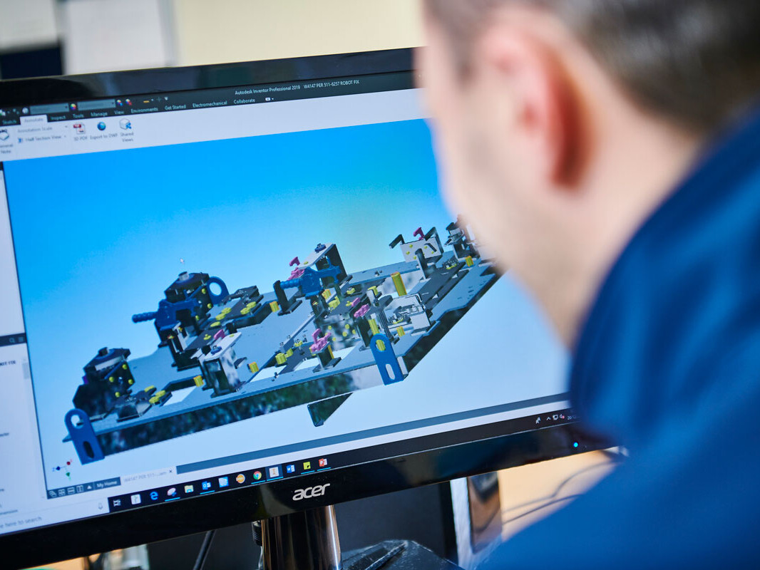
Autodesk Inventor Info
Autodesk Inventor is a 3D mechanical solid modelling design software developed by Autodesk to create 3D digital prototypes. It is used for 3D mechanical design, design communication, tooling creation and product simulation. This software enables users to produce accurate 3D models to aid in designing, visualizing and simulating products before they are built.
It incorporates integrated motion simulation and assembly stress analysis, whereby users are given options to input driving loads, dynamic components, friction loads and further run the dynamic simulation to test how the product will function in a real-world scenario. These simulation tools enable users designing cars or automotive parts, for example, to optimize the strength and weight of a product, identify high-stress areas, identify and reduce unwanted vibrations, and even size motors to reduce their overall energy consumption.
Autodesk Inventor’s finite element analysis feature allows users to validate the component design through testing part performance under loads. The optimization technology and parametric studies permit users to design parameters within assembly stress areas and compare the design options. Then, the 3D model is updated based on these optimized parameters.
Our Engineering Team also utilises TruTops Boost software for laser nesting as well as programming on our TruBend 230S.
Boost Info
TruTops Boost, the new software solution developed by Trumpf, merges into a single system all the steps needed to generate sheet metal manufacturing programs. This includes everything from part design and data import to nesting and even writing NC programs for cutting, punching and bending. The new operating reasoning makes TruTops Boost easy to understand and, thanks to the Boost Technology, makes it unbeatably fast since the calculations are carried out automatically.
With TruTops Boost, designing and programming for sheet metal processing are made much simpler. The new Trumpf software is based on an entirely new operating philosophy. The program steps the operator through the process and provides support in numerous automatic features. Here, a single system, working on the basis of the job order, handles the design, generates an unfolding, and prepares NC programs for 2D laser cutting, punching and bending. No longer is it necessary to place information in intermediate storage and call it up in various applications.
A jig is a type of tool used to control the location or motion of another tool. A fixture, on the other hand, is a support or work holding device used to fix the object in place. In metal and woodworking, both jigs and fixtures are essential tools. Many often confuse the two but they are two distinct tools with very different functions.
A jig is typically described as a plate, box or open frame used for holding work and guiding machine tools to the work. The main objective of a jig is to provide repeatability, interchangeability and accuracy in the manufacturing process. The most common form of jig is the drill jig, which guides the drill bit to the desired hole location.
A fixture describes the various devices used to hold work in a machine tool. It is a supporting device that is quite large and permanently attached to the work surface. The main objective of a fixture is to ensure that the workpiece is stable and does not move during machining, assembly or welding. A fixture can be unique and built to fit a particular part or shape.
There are also devices that do both the work of a jig and fixture. These are called jigs, which is also why many get confused and find it hard to tell the two apart. There are many types of jigs, some of which includes machining jigs, robot jigs, welders’ jigs, jeweller’s jigs and so on. Some types of jigs are also known as templates or guides.
Just like jigs, there are also various types of fixtures, including general purpose and specialised. Fixtures that are used for general purposes are usually relatively inexpensive and can hold a variety of dimensionally different workpieces. Some examples are vices, chucks and split collets. On the other hand, fixtures can be designed for a special purpose – such as holding specific workpieces for a specific operation on a specific machine or process.
The primary purpose of jigs and fixtures are that they help reduce the cost of production, maintaining consistent quality and maximising efficiency. They enable a variety of parts to be made to correct specifications and reduce operator errors. As they result in increased productivity, easy assembly, reduction in waste and savings in labour cost, jigs and fixtures can substantially reduce the total cost of producing a product.
Poka-Yoke is a Japanese term that translates to “mistake-proofing” or “inadvertent error prevention”. A poka-yoke is a mechanism within a process that helps an equipment operator avoid (yokeru) mistakes (poka). Its purpose is to eliminate product defects by preventing, correcting, or drawing attention to human errors as they occur and preventing the operator from proceeding without rectification.
Correcting defects once they reach the customer is very costly. Every effort must be made to capture defects as early on in the process as possible. It is this early error detection and prevention that makes Poka-Yoke such a powerful tool. The main aim of Poka-Yoke is to ensure that each stage in the chain maintains the expected quality, preventing defects from ever reaching the customer.
Here at Newfield, we utilise the three main methods of Poka-Yoke:
Contact: This method of Poka-Yoke enforces product specification through physical means. For example, if a product has a round shape, the jig holding it would be circular and any other shape would stop the process. Other product qualities such the size, colour and type of material are useful for this kind of mistake-proofing. Sensors on the workbench can detect whether a piece is placed correctly and will stop the process if not.
Constant Value: As the name suggests, this type of Poka-Yoke is triggered when a set quantity is not attained in the process. Here, a process must achieve a predetermined number of steps for it to be considered to be within specifications. Sensors that check if the count meets specifications and reports accordingly.
Sequential: The manufacturing of a product involves a sequence of steps that must be followed in the correct order. This type of mistake-proofing detects whether the preceding step has been done correctly.
In terms of Jigs/Fixtures, this means that we consider any variations that could occur during the assembly process and address these in the design of the tooling to prevent operators making mistakes when assembling the products.
In terms of machinery this means that wherever possible, we add numerical/sequential counters to the machine to verify the number of parts produced.
We also utilise checking fixtures throughout the factory as gauges to ensure the parts conform to their dimensional requirements.
Coatings
Depending on part visibility and performance requirements, we have a number of coating processes at our disposal. We offer on-site wet spray and powder coating as well as off-site zinc-plating and electrophoretic painting galvanising. We also provide two pre-treatment services, shot-blasting and zinc-phosphate, the selection of which depends on the part and the chosen coating.
The service life of a coating is greatly improved by effective pre-treatment. It essential that all mill scale, rust and previous coatings have been totally removed prior to painting and coating, allowing greater adhesion to the part’s surface.
To ensure the durability of our coatings, our processes are continuously monitored through Newfield’s Quality Management System and frequently reviewed for improvement. Our processes are certified to IATF 16949 and our team undergoes continuous training to ensure best practice and consistent high-quality finishes. At Newfield, quality control and traceability are paramount, and we have implemented a number of systems to ensure our customers.
Powder Coating
For many of our customers, powder coating is an essential part of their manufacture process, providing both elemental protection and a high-quality aesthetic finish. Newfield offers a diverse selection of powder coating colours at its satellite purpose-built site less than 400 metres from our main facility. We conduct regular quality checks to ensure that all powder coating is carried out to customer specifications and only use powders supplied by recognised manufacturers. Conforming with the rest of our facility, full traceability and compliance with IATF 16949 and ISO 9001 are maintained throughout the metal powder-coating process.
Once the parts have completed and passed their visual inspections, they will either be packaged to customer specifications or transported back to our main site for additional engineering operations, dependent on the specifications of the part.
Benefits of powder coating:
- Powder coating provides a long-lasting, economical, and durable finish with a range of colour options available.
- Powder-coated surfaces are more resistant against scratches, chipping, wear, and fading than other types of finishes.
- It is more environmentally friendly as it does not use solvents and produces few volatile organic compounds.
- As the powder is very fine, it is possible to apply thicker coats without running or clogging. It is typically a one-coat finish.
- The powder coating process includes curing in an oven, creating a protective layer that is much harder than conventional liquid paint.
- Powder coating creates a very even surface finish, vertically and horizontally, because it is sprayed and heated without drips or application traces.
Limitations of powder coating:
- It is harder to achieve a thin finish with metal powder coating.
- The time taken for a colour change is considerably higher for powder coating than wet spray painting, but this includes the time required to perform the quality checks necessary to maintain a high standard of finish.
Wet Paint
Wet paint is the ‘traditional’ process of applying liquid paint to a metal product for finishing. The part is first shot-blasted, with small abrasive particles propelled toward the surface to provide a thoroughly clean substrate for the wet painting. Once the surface has been prepared, the liquid paint is applied using a spray, pump or pressurised vessel to deliver it evenly. It is applied until the product is evenly coated with the desired thickness, usually 15-20µm.
[need some info on Newfield’s capacity/booths/equipment/staff/standards]
Benefits of wet spray:
- Wet spray painting is particularly useful for large, heavy or awkwardly shaped objects that cannot be hung for powder coating.
- The process is very efficient for large components.
- It is a cost-effective finish, significantly more economical than some alternatives – particularly for low production runs.
- Colour selection is practically infinite, providing the opportunity to match branding or aesthetic requirements. Toning is very precise, making colour matching a possibility.
- It can be applied to a range of materials and is ideally suited to heat-sensitive parts that cannot be powder coated.
- The paint applied is a much thinner coating than other processes, which may benefit lightweight or precision parts.
- Wet spray painting allows you to air-dry or bake your product for finishing.
- It is possible to achieve a variety of gloss levels and paint textures, applying them consistently for a high-quality finish across the entire surface area.
Limitations of wet spray:
- The process itself is not as efficient; powder-coating typically has a transfer efficiency of 60-70%, whereas wet spray is approximately 30-35%.
- It is less environmentally friendly due to the chemicals in the paint.
- The thinner coat of wet spray paint means that it is not as durable as powder coating.
- It may require multiple coats to achieve an even surface finish.
More Information
What is Powder Coating?
Powder coating is a dry finishing process that has become extremely popular since its introduction in the 1960s, with the global powder coating market expected to reach £9.66bn by 2020. Powder Coating represents over 15% of the total industrial finishing market and is used on a wide array of products.
It is growing popularity thanks to its high-quality, corrosion-resistant finish and aesthetic appearance.
The main difference between a conventional liquid paint and a powder coating is that the powder coating does not require a solvent to keep the binder and filler parts in a liquid suspension.
Intricate fabricated metal shapes can be powder coated evenly and without sagging, allowing for much thicker coats when compared to paint finishes. Powder Coating can be used for both functional and decorative finishes, with an almost limitless number of colours and textures available.
How powder coating works
Powder coatings are based on polymer resin systems, combined with curatives, pigments, levelling agents, flow modifiers, and other additives. These ingredients are melted, cooled, and ground into a uniform powder similar to baking flour. A process called Electrostatic Spray Deposition (ESD) is typically used to achieve the application of the powder coating to a metal substrate. This application method uses a spray gun to apply an electrostatic charge to the powder particles, each of which is then attracted to the grounded part.
After application of the powder coating, the parts enter a curing oven where, with the addition of heat, the coating chemically reacts to produce long molecular chains, resulting in high cross-link density. These molecular chains are very resistant to breakdown and give powder coating its mechanical properties. This type of application is the most common method of applying powders.
Powder coating is based on the principle that objects with opposite electric charges (positive and negative) attract one another. The powder particles are negatively charged after passing through the special spray gun, making them attracted to the earthed part achieving high levels of adhesion and consistency.
Most conducting or thermally stable materials are suitable for powder coating, metals are particularly good due to their high electrical and thermal conductivity. Even complex metal components can be powder coated evenly, with excellent adhesion.
The durability of powder coating
Powder coating is a high-quality finish found on thousands of products you come in contact with each day. It protects the roughest, toughest machinery as well as the household items you depend on daily. It provides a more durable finish than liquid paints can offer, while still providing an attractive finish. It is a tough coating that can resist impact, moisture, chemicals, ultraviolet light, and other extreme weather conditions, reducing the likelihood of scratches, chipping, abrasions, corrosion, fading, and other wear issues.
Pre-treatment process for powder coating
Unlike Iron-Phosphate treatments, Zinc-Phosphate is unable to clean and coat simultaneously and so our 8-stage Zinc-Phosphate process includes cleaning, rinsing and conditioning stages. The reason that we use Zinc-Phosphating over Iron is that Zinc-Phosphate coatings are extremely adherent, they provide a uniform coating with improved coating adhesion properties, better coating in recessed areas and better corrosion resistance and have been widely used in the automotive sector for many years.
Prior to parts undergoing the Powder Coating process, they must first be pre-treated and at Newfield, we operate a Zinc Phosphate pre-treatment process which is comprised of 8 quality-controlled stages:
Stage 1 – Clean
This stage of the pre-treatment process ensures that the parts are free from any residual surface residue such as rust preventative oils and lubricants, machining oils, rolling mill or heat scale, metallic fines and laser scale.
Stage 2 – Rinse
This stage ensures that the part is now free from any excess chemicals from the previous stage and requires the basket to be submerged in constantly agitated clean water for 1 minute.
Stage 3 – Acid
This stage removes any imperfections around the edges of the parts caused by the laser cutting process and ensures any remaining surface contaminants are removed. This process is stringently controlled and monitored through our pre-treatment quality checks which themselves are audited weekly to verify all results.
Stage 4 – Rinse
This stage ensures that the part is now free from any excess chemicals from the previous stage and requires the basket to be submerged in constantly agitated clean water for 1 minute.
Stage 5 – Activate
This stage is used to provide a very uniform micro-crystalline coating which provides maximum effectiveness in the Zinc Phosphate stage.
Stage 6 – Phosphate
This stage involves a chemical reaction between the substrate and the Zinc-Phosphate and is used to provide a uniform crystal layer which the powder then adheres to during the Powder Coating process.
Stage 7 – Rinse
This stage ensures that the part is now free from any excess chemicals from the previous stage and requires the basket to be submerged in constantly agitated clean water for 1 minute.
Stage 8 – Dry
This stage requires the basket to be contained within an oven for 20-30 minutes (dependent on the properties of the part in question) to ensure the part is free from any liquids and that the part is dry and ready to be moved to our paint-line.
Get in touch to learn how Newfield Fabrications can enhance your next project.
CNC Machining
Precision Machining Services
We offer numerous manual and CNC machining services, each backed by our rigorous quality standards and adherence to IATF 16949. Alongside investment in advanced equipment, our precision machinists undertake continuous training to develop a comprehensive skill set. As such, we can work with a wide variety of materials, from common metals like aluminium and steel through to plastics, foams and composites.
Newfield has two primary Computer Numerical Control (CNC) machines, Unisign’s Univers 6000 and Univers 4000. These are used alongside various other machines including a CNC lathe, manual lathe, air tapping drill, pedestal drill and a KRV milling machine.
The Univers 6000 combines powerful multi-sided precision machining with high dynamics, accuracy and flexibility. It is particularly well suited to large or long workpieces like beams and traverses, axles and trailer side members. It has been used to produce parts for a variety of industries, including oil and gas, commercial vehicle, rail and energy.
The Univers 6000 can maintain accuracy and performance over its entire work envelope, even large workpieces up to 8 metres in length. It can work on toughened materials, accepts large tool diameters and the unique right-angle head allows for multi-sided CNC machining. The large 3 x 0.8 x 0.6 metre working area can also be divided into two zones for pendulum machining, further increasing efficiency.
The Univers 6000’s accuracy is thanks to precise machine geometry and a short distance between the spindle centre line and the Z-axis guide ways – providing high rigidity. The main drive is water-cooled for thermal stability and overall rigidity ensures repeatable operation and manufacture to prescribed tolerances.
Alongside the 6000, our machinists also use a Univers 4000 vertical CNC machining centre. It is a much more compact system, with a working area of 1.6 x 0.6 x 0.5 metres but is also capable of pendulum machining. It features very high accuracy thanks to precise linear guides on all axes and an automatic tool change from 51 storage pockets.
More Information
Computer numerical control machining, or CNC machining, is the automated removal of material from a block, such as plastic or metal, resulting in a finished part.
A computer converts the design produced by Computer-Aided Design software (CAD), into numbers – or, more correctly, coordinates. The computer uses these coordinates to control the movement of the various tools to remove material and shape the part. The process is also known as subtractive manufacturing and can use a range of complex machinery, from grinders and lathes to mills and routers.
Thanks to its high level of automation, precisoin CNC machining is price-competitive for both one-off custom parts and medium-volume productions. The parts it produces are very accurate with excellent physical properties.
Almost every material can be CNC machined. The most common examples include metals (Aluminium and Steel alloys, brass etc) and plastics (ABS, Delrin, Nylon etc). Foam, composites and wood can also be machined.
The basic CNC process can be broken down into 3 steps.
- The engineer first designs the CAD model of the part
- The machinist then turns the CAD file into a CNC program (G-code) and sets up the machine
- Finally, the CNC system executes all machining operations with little supervision, removing material and creating the part
About the milling process
Milling is the machining process in which rotary cutters are used to remove material by advancing a cutter into a workpiece. This may be done while varying direction on one or several axes, cutter head speed, and pressure. Milling covers a wide variety of different operations and machines, on scales from small individual parts to large, heavy-duty gang milling operations. It is one of the most commonly used processes for machining custom parts to precise tolerances.
Our CNC milling process uses 3-axis milling and 5-axis indexed milling to rapidly cut a choice of more than 30 engineering-grade thermoplastics and metals into complex shapes and precision components.
About the turning process
Turning is a form of machining, a material removal process, which is used to create rotational parts by cutting away unwanted material. The turning process requires a turning machine or lathe, workpiece, fixture, and cutting tool. The workpiece is a piece of pre-shaped material that is secured to the fixture, which itself is attached to the turning machine, and rotated at high speeds. The cutter is typically a single-point cutting tool that is also secured in the machine, although some operations make use of multi-point tools. The cutting tool feeds into the rotating workpiece and cuts away material in the form of small chips to create the desired shape.
Turning is used to produce rotational, typically axis-symmetric, parts that have many features, such as holes, grooves, threads, tapers, various diameter steps, and even contoured surfaces. Parts that are fabricated completely through turning often include components that are used in limited quantities, perhaps for prototypes, such as custom-designed shafts and fasteners. Turning is also commonly used as a secondary process to add or refine features on parts that were manufactured using a different process. Due to the high tolerances and surface finishes that turning can offer, it is ideal for adding precision rotational features to a part whose basic shape has already been formed.
Our CNC turning process uses a rod stock, in a choice of metal materials, which is rotated against live tooling to create final parts with axial and radial holes, flats, grooves and slots.
Assemblies
We have 60 years of experience as a leading fabrication company. From construction equipment to rail, automotive, nuclear and recycling, our expert fabricators are relied upon in almost every sector. Continuous investment in training and technology has placed us at the forefront of the metal fabrication industry and established our reputation as an ideal manufacturing partner. Our fabrications meet stringent internal quality control and we are accredited to IATF 16949 – the world’s foremost quality standard for the automotive industry.
MIG, TIG or robotic? We offer a range of fabrication and welding services based on our team’s extensive experience and modern equipment. Our in-house welding processes include MIG, TIG, robotic, spot, stud and projection welding, with our dedicated engineering team able to select the most appropriate method for the part you require.
We can also provide finishing operations, using grinding and sanding techniques to ensure that your parts have the desired surface finish.
Our highly qualified and experienced operators work in advanced, purpose-built welding bays and can undertake both large and small-scale projects. Our dedicated engineering team are trained to follow the Value Analysis Value Engineering (VAVE) process. The technique allows them to significantly reduce the number of components in complex fabrications or minimise the number of required processes, using advanced bending to create your parts at a reduced cost.
With just in time (JIT) and Kanban manufacturing capability, Newfield is able to deliver high-quality fabrications precisely when required. Newfield’s continuous investment in equipment and technology has resulted in lean processes and highly capable low-cost manufacturing. We can use a number of quality verification tools, including process failure mode effects analysis (PFMEA), control plans and 8D problem-solving.
Our expert welders are also specialists in one-offs, prototypes and low-volume products, with a capacity for large fabrications up to 10 tonnes. For cost-effective manufacture, we minimise tooling and fixturing, instead relying on the experience and knowledge of our skilled welders to complete the parts to Newfield’s demanding quality standards. If the part is highly complex, then it may be necessary to use a fixture. Likewise, we are open to using a fixture if specifically requested by the customer or fabricating hand-built projects without one.
Robotic welding is a pioneering process that offers increased efficiency through faster and more consistent cycle times. Our six-axis high-performance robots bring speed, reliability and precision to much of our welding work.
We typically use robotic welding for large production volumes and parts required on regular schedules. The process is ideally suited to these applications as the higher cost is mitigated by the volume of output. If quality is paramount, however, then there are significant benefits to using robotic welding for low and medium volume production runs, as well as single items.
We have developed a significant robot welding capacity, with seven robots onsite, two of which were replaced in 2019 in a £150,000 investment.
Our robots can handle metal fabrications up to 5 tonnes and workpieces 8m long and 2.4m in diameter. All of our robots feature two workstations, allowing one piece to be set up while another is being welded, improving efficiency for large assemblies.
Newfield’s welders use both Metal Inert Gas (MIG) and Tungsten Inert Gas (TIG) in a variety of medium to high volume applications, all certified to IATF 16949. We are able to provide Just in Time (JIT) supply, Kanbans and implement Enterprise Resource Planning (ERP).
From support with product design through to cost reductions via a Value Analysis and Value Engineering (VAVE) process, Newfield can work with you from the beginning to hit quality, design and budget targets.
Newfield’s welders receive continuous training to maintain their exceptional level of work. While each process has its advantages, our welders maintain a number of skill sets allowing us to easily accommodate a variety of different projects.
We also ensure our welders have the right equipment and have recently invested in new ESAB MIG welding sets. We believe that providing our professionals with the right tools is essential to the standard of work we produce.
Read our handy guide to the differences between MIG and TIG welding.
More Information
1. Increase in Productivity
Robot welding is often a fast process because it can operate continuously, withstanding a greater arc on-time and moving quickly between weld joint positions. A robotic welding system can provide substantial increases in output.
2. Consistent and Repeatability
Manual welding requires a high level of skill and concentration to achieve reliable consistency. A robotic welder can continue to perform precisely the same weld cycle continuously, 24 hours a day, seven days a week. This is particularly important for complex welds with restricted access, where a robot is able to maintain much greater control.
3. Flexibility
Our robots can be programmed with a vast number of parts, enabling us to simply swap the jig on the robot bed, load the materials and begin the programme.
4. Safety
Robotic welding can improve safety through the reduction of handling and operating within an enclosed cell.
5. Quality
A robotic welder can achieve superior quality by ensuring the correct welding angle, speed, and distance, with repeatable accuracy of ±0.04mm. Ensuring that every welding joint is consistently produced to a very high standard significantly reduces the risk of costly rework.
6. Labour
Robotic welding systems are ideal for alleviating workload during busy periods. These systems allow less experienced welders to consistently perform high-quality welds. Our robot operators are all highly experienced and understand the distinct advantages of using our robotic systems.
7. Reduce Consumables
The consistency of robotic welding allows us to optimise the welding processes, reducing costs associated with welding consumables.
8. Reduced Production Costs
Through improvements in quality, consistency and productivity, a robotic welding system can deliver parts at a reduced cost. Further savings can be made through reduced energy consumption and consumable costs, alongside decreased labour and insurance costs.
9. Reduction in Weld Distortion
Distortion in a weld is due to the expansion and contraction of the weld metal and the adjacent base metal during the heating and cooling cycle of the welding process. A manual process is less repeatable – meaning two qualified welders will have slightly different techniques. If there is a difference in the heat applied, it can create distortions. Robotic welding is both accurate and repeatable, reducing the risk of differences between welds and ensuring consistency.
10. Increased Competitive Advantage
Implementing a robotic welding solution can set companies apart from the competition, allowing for faster completion and delivery of products whilst ensuring consistent quality.
MIG Welding
MIG welding is an abbreviation for Metal Inert Gas welding, also known as Gas Metal Arc Welding (GMAW). It is a process developed in the 1940s and is considered semi-automated.
MIG welding requires three things; electricity to produce heat, an electrode to fill the joint, and shielding gas to protect the weld from the air. MIG welding is done using a very small electrode that is fed continuously, while the operator controls the amount of weld being produced.
The equipment used automatically regulates the electrical characteristics of the arc. The only manual controls required of the welder in semi-automatic operation are travel speed, travel direction and gun (torch) positioning.
Given proper equipment settings, the power supply will provide the necessary amperage to melt the electrode at the rate required to maintain the pre-selected arc length (voltage). As the welder squeezes the trigger of the MIG gun, the electricity charges the electrode while the feeder starts feeding the filler wire, creating the weld material. The shielding gas is also fed through the MIG gun nozzle, isolating the weld from the surrounding air and preventing contamination.
Filler metal selection is closely matched to the base material. The filler metal not only conducts electrical current to the arc zone, melting the base metal and electrode, it also adds reinforcement to the completed weld joint.
MIG Welding can be used with a wide variety of metals and base metal thicknesses. Its successful application depends on the appropriate selection of:
- Electrode – composition, diameter and packaging
- Shielding Gas – type (composition), purity and flow rate
- Process Variables – current, voltage, mode of metal transfer and travel speed
- Equipment – power source, welding gun and wire feeder
TIG Welding
Tungsten Inert Gas (TIG), also known as gas tungsten arc welding (GTAW), was originally created by the aircraft industry to weld magnesium in the 1930s and 1940s. It uses the heat generated by an electric arc struck between a non-consumable tungsten electrode and the workpiece. This heat fuses the metal in the joint area and produces a molten weld pool. The arc area is shrouded in an inert gas shield to protect the weld pool and the electrode from oxygen contamination.
The process may be operated autogenously, that is, without filler, or filler may be added by feeding a consumable wire or rod into the established weld pool. TIG produces very high-quality welds across a wide range of materials with thicknesses up to about 8 or 10mm. It is particularly well suited to the welding of sheet material.
One of the greatest advantages of TIG welding is the amount of control it allows. A welder can control heat and amperage with precision using a foot or thumb remote control switch. The TIG gun is thin, which adds to the control a welder can have over the process.
The success of TIG welding hinges on various factors such as the choice of shielding gas, welding wire, tungsten electrode and the user’s technique. The finished product is a sound, slag-free weld that shares the same corrosion resistance properties as the parent metal.
The Differences Between MIG and TIG Welding
MIG and TIG welding both use an electric arc to fuse metal components together. The major difference between MIG and TIG welding is that one process uses a continuously feeding wire (MIG) and the other uses long welding rods that are slowly fed into the weld pool (TIG). TIG is by far the more difficult to learn but both are hard to master.
A MIG welder works by using a continuously feeding spool of welding wire that burns, melts and fuses both the base and parent metals together. You can weld a variety of materials such as mild steel, stainless steel and Aluminium. A range of material thicknesses can be welded from thin gauge sheet metal right up to heavier structural plates. Because it uses filler material, MIG welding often performs better for welding thicker objects, since it doesn’t have to heat the material all the way through to form a bond. Also, the use of filler material makes it slightly easier to control than TIG welding.
TIG welding, on the other hand, can join objects without filler by heating the surfaces to the point where they bond, creating neater welds. It does, however, require a great degree of precision to avoid over-heating the metal, which can cause stress cracks and other issues. TIG welding is more commonly used for thinner gauge materials and is used for things like kitchen sinks and toolboxes. The biggest benefit is that you can use relatively low power and avoid blowing through the metal. It is a much finer and delicate technique that results in a more aesthetic weld.
Get in touch to learn how Newfield Fabrications can enhance your next project.
Contact
Well Located
Newfield Fabrications is just five minutes from junction 17 of the M6 motorway in Cheshire. We can provide delivery to anywhere in the UK using our own fleet of vehicles. Get in touch to find out why Newfield Fabrication is your ideal fabrication partner.
Get in Touch
Please leave us a message using the form provided and we will respond shortly.
Alternatively call: 01270 762331.
Quality
Our Accreditations
Newfield Fabrications is accredited to both IATF 16949 and ISO 9001:2015 standards. We have earned a reputation for the quality of our work and strive to maintain this with all our customers. We have an established ‘zero waste’ culture and strive to minimise risk through our data-driven continuous improvement processes.
Our Team
Our Quality Team has over 200 years’ experience in the industry. Their ability to rapidly respond to any quality issues that might arise during production is central to Newfield’s high standards. Not only do they carry out routine component inspection, but they are also able to use portable equipment to carry out spot checks at any point in the production process. Each member of the team is trained in the key quality tools associated with IATF 16949, including measurement techniques, auditing, the use of PFMEA, control plans and standard operating procedures.

Our Equipment
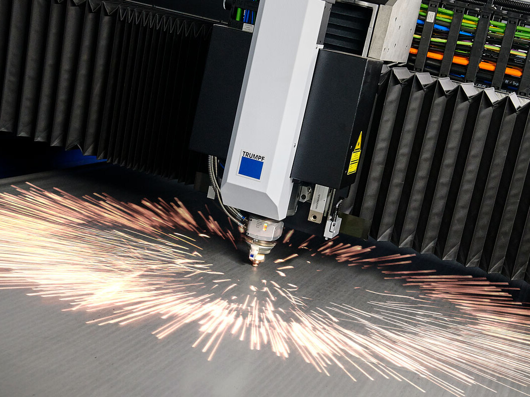
Our ongoing investment in the latest equipment and tools keeps Newfield at the forefront of the fabrication industry. From our advanced 10kW laser cutter to our 230-tonne automated bending machine, we believe that to provide our customers with the highest possible quality products we must equip our skilled operators with class-leading equipment. Our ongoing investment in automated processes reduces the risk of errors and helps to improve product consistency. We conduct regular measurement system analysis (MSA) studies and monitor the process capability index (CPK) of all our processes, taking action accordingly.
Our Philosophy
Here at Newfield, we understand that Safety is paramount in any work environment. We also understand that in order to work safely, processes must be as robust as possible – considering any potential risks to individuals, equipment and products. For this reason, our entire Quality Management System is designed around the Plan, Do, Check, Act methodology.
Problem-Solving
We understand that mistakes and errors are a possibility, but we know the importance of rectifying them as quickly and effectively as possible. Our Continuous Improvement philosophy emphasises problem-solving and the prevention of recurrence. However, we do not just apply it to mistakes, it is also utilised as an improvement tool to map processes and remove any non-value added (NVA) operations – reducing customer costs. Newfield operates using the 8D problem-solving method, with all Team Leaders trained to implement the technique.
More Information
The Eight Disciplines of Problem Solving (8D) is a problem-solving methodology designed to find the root cause of a problem, devise a short-term fix and implement a long-term solution to prevent recurring problems. When it’s clear that your product is defective or isn’t satisfying your customers, an 8D is an excellent first step to improving Quality and Reliability.
Ford Motor Company developed this problem-solving methodology, then known as Team Oriented Problem Solving (TOPS), in the 1980s. The 8D problem-solving process is a detailed, team-oriented approach to solving critical problems in the production process. The goals of this method are to find the root cause of a problem, develop containment actions to protect customers and take corrective action to prevent similar problems in the future.
The strength of the 8D process lies in its structure, discipline and methodology. 8D uses a composite methodology, utilising best practices from various existing approaches. It is a problem-solving method that drives systemic change, improving an entire process in order to avoid not only the problem at hand but also other issues that may stem from systemic failure.
Training
All of our production Team-Leaders have received external training on Problem Solving techniques based around the Global 8D concept. This ensures that when a problem occurs, they are able to offer invaluable insight into potential causes as well as solutions and are actively involved in problem-solving.
How do we apply it?
As stated previously, all our Team-Leaders have received training on problem-solving and Global 8D, but how do we utilise this? Here at Newfield, we accept that as humans, we can make mistakes. And when this happens, we need to act quickly to identify what the cause was and implement corrective actions to prevent a recurrence. In order to do this, we have a bespoke system in place that tracks all quality concerns reported both internally and externally.
Our 8D methodology:
Stage 1 – Define the problem
Before you can fix any problem, you must define what this problem is (who, what, where, when); this is part of the “Plan” process within the PDCA methodology.
Stage 2 – Select your team
Because of the training received, our Team-Leaders and their operators are involved very early on. Typically, our problem-solving teams consist of the Team-Leader of the process, the operators involved, a member of our Engineering team, at least one member of the Quality Team and a member of the Continuous Improvement Team. This team is typically the same team as those involved in the PFMEA and Control Plan reviews mentioned earlier.
Stage 3 – Contain
This stage must be completed within 24 hours of the problem being reported and involves checking all inventory on-site for the issue as well as any WIP (Work in Progress). This stage also involves putting a system in place temporarily to prevent any escapes to the customer whilst the root cause is determined and actioned.
Stages 4 & 5 – Root Cause
At Newfield, we focus on two elements of Root Cause Analysis; how did it happen and how did it escape? This ensures that wherever possible, we implement actions to prevent recurrence of the fault, but we also address why the fault was not detected at the time it occurred. This is done using various problem-solving techniques such as 5Why’s, Fishbone diagrams and process flows to identify any variation in the process that can be eliminated.
Stage 6 – Implementation of Corrective Action
Now that the Root Cause has been determined, the team must plan the required corrective action and then implement.
Stage 7 – Verification
This stage involves a member of the Quality team ensuring that any corrective action is effective and efficient and that the Root Causes have been addressed.
Stage 8 – Read-Across
At this stage, we look at how the problem occurred and how it was solved and see if it can be applied to similar parts and/or processes to prevent problems before they occur. This is part of our Continuous Improvement ideology here at Newfield.
All 8Ds raised are documented along with any evidence such as photos and are trended within our problem-solving system to identify any common areas which require improvement. This also involves conducting Pareto analysis on a regular basis and providing feedback to the production team.
Production Part Approval Process (PPAP) is an invaluable quality tool used in order to provide customers with a detailed understanding of the processes to be used to manufacture their product(s). In today’s competitive manufacturing environment, we understand that controlling cost and maintaining a high level of quality have become vital to success. Therefore, it has become imperative to provide quality parts that meet the customer’s requirements the first time and every time.
Elements of PPAP
Below is the list of all 18 elements accompanied by a brief description for each element:
1. Design Documentation
Design documentation shall include both a copy of the customer and our drawings as well as a copy of the Purchase Order (PO). The PO is used to confirm that the correct part is being ordered and that it is at the correct revision level. The design engineer is responsible for verifying that the two drawings match and all critical or key characteristics have been identified.
Material composition information is required to supply evidence that the material used to manufacture the parts meets the customer’s specific requirements.
2. Engineering Change Documentation
If the PPAP is being required due to a request for a change to a part or product, the documentation requesting and approving the change must be included in the PPAP package. This documentation usually consists of a copy of the Engineering Change Notice (ECN), which must be approved by the customer engineering department.
3. Customer Engineering Approval
When required as part of the PPAP, we will provide evidence of approval by the customer engineering department. If required, pre-PPAP samples are ordered by the customer for onsite testing. The samples must be production intent and ship with a waiver so that testing can be done. When testing is complete, the test engineers will provide an approval form for inclusion in the PPAP submission.
4. Design Failure Mode and Effects Analysis
Design Failure Mode and Effects Analysis (DFMEA) is a cross-functional activity that examines design risk by exploring the possible failure modes and their effects on the product or customer and their probability to occur. These failure modes can include:
- Product malfunctions;
- Reduced performance or product life;
- Safety and Regulatory issues.
5. Process Flow Diagram
The Process Flow Diagram outlines the entire process for assembling the component or final assembly in a graphical manner. The process flow includes incoming material, assembly, test, rework and shipping.
6. Process Failure Mode and Effects Analysis
Process Failure Mode and Effects Analysis (PFMEA) reviews all of the steps in the production process to identify any potential process quality risk and then document the applied controls. The PFMEA is also a living document and should be updated even after the product is in normal production.
7. Control Plan
The Control Plan is an output from the PFMEA. The Control Plan lists all product Special Characteristics and inspection methods required to deliver products that continually meet the customer quality requirements.
8. Measurement System Analysis Studies
Measurement System Analysis (MSA) studies will include Gage Repeatability & Reproducibility (GR&R) studies on measurement equipment used during assembly or quality control checks. Calibration records for all gages and measurement equipment must be included.
9. Dimensional Results
The dimensional layout of sample parts is required to validate the product meets the print specifications. The samples should be randomly selected from a significant production run usually at least 30 pieces. Each dimension on the drawing is measured on the final assembly to make sure that it falls within specification. The results are recorded in a spreadsheet and included within the PPAP submission.
10. Records of Material / Performance Tests
This element should contain a copy of the Design Verification Plan and Report (DVP&R). The DVP&R is a summary of every validation test performed on the part. It should list each and every test performed, a description of how the test was performed, and the results of each test.
This section typically includes copies of all the certification documents for all materials listed on the prints. The material certification shall show compliance to the specific call on the print.
11. Initial Process Studies
Initial process studies will be done on all the production processes and will include Statistical Process Control (SPC) charts on the critical characteristics of the product. These studies demonstrate that the critical processes are stable, demonstrate normal variation and are running near the intended nominal value.
12. Qualified Laboratory Documentation
Qualified laboratory documentation consists of the industry certifications for any lab that was involved in completing validation testing. This could be for an in-house test lab or any offsite contracted test facilities that were used for validation or material certification testing.
13. Appearance Approval Report
The Appearance Approval Inspection (AAI) is applicable for components affecting appearance only. This report verifies that the customer has inspected the final product and it meets all the required appearance specifications for the design. The appearance requirements could include information regarding colour, textures, etc.
14. Sample Production Parts
Sample production parts are sent to the customer for approval and are typically stored at either the customer or supplier’s site after the product development is complete. A picture of the production parts is usually included in the PPAP documentation along with documentation regarding the location that the parts are being stored.
15. Master Sample
A master sample is a final sample of the product that is inspected and signed off by the customer. The master sample part is used to train operators and serves as a benchmark for comparison to standard production parts if any part quality questions arise.
16. Checking Aids
This is a detailed list of checking aids used by production. It should include all tools used to inspect, test or measure parts during the assembly process. The list should describe the tool and have the calibration schedule for the tool. Checking aids may include check fixtures, contour, variable and attribute gages, models or templates.
MSA may be required for all checking aids based on customer requirements.
17. Customer Specific Requirements
This element of the submission package is where any special customer requirements are contained. For bulk materials, the customer-specific requirements shall be recorded on the “Bulk Material Requirements Checklist”.
18. Part Submission Warrant
The Part Submission Warrant (PSW) form is a summary of the entire PPAP submission. A PSW is required for each of part number unless otherwise stated by the customer. The PSW includes:
- The reason for submission (design change, annual re-validation, etc.);
- Supplier authorized person signature along with contact information;
- A section provided for any required explanation or comments;
- An area for the customer to indicate the disposition of the PPAP;
- Declaration of part conformity to customer requirements;
- The level of documents submitted to the customer.
The PPAP process is a detailed and lengthy process. The PPAP package includes documentation of various multiple cross-functional tools and documents our ability to meet all customer requirements. The PPAP provides customers adequate information to validate that all areas of the design and production processes have been reviewed thoroughly to ensure that only high-quality products will be allowed to ship to the end customer
The Plan, Do, Check, Act (PDCA) methodology is one of the original quality tools and is the foundation for ISO 9001:2015. Put simply, it means that any time a process is being reviewed or developed, you must consider all factors that could cause risk and act accordingly to mitigate the risk as far as reasonably practicable. This applies to Quality as well as Safety and that is why here at Newfield, we consider ourselves to be ever-learning and ever-developing because we understand that everything can always be improved, and we continually seek to do so.
Official PDCA
The PDCA Cycle can help differentiate a company from its competition, especially in today’s corporate world, where anything that can help them streamline their processes to reduce costs, increase profits and improve customer satisfaction can give them an advantage. Whether they know it or not, many managers use the PDCA Cycle to help direct their organizations, as it encompasses the very basic tenants of strategic planning. The four components can be summarised like the following:
Plan: A well-defined project plan provides the framework from which to operate. Importantly, it should reflect the organisation’s mission and values. It should also map the project’s goals and clearly indicate the best way to meet them.
Do: This the step where the plan is set in motion. The plan was made for a reason, so it is important for players to execute it as outlined. This stage can be broken down into three sub-segments, including training of all personnel involved in the project, the actual process of doing the work and recording insights, or data, for future evaluation.
Check: Typically, there should be two checks throughout the project. First, checks should be done alongside the implementation to make sure that the project’s objectives are being met. Second, a more comprehensive review of the project should be done upon completion to allow for successes and failures to be addressed, and for future adjustments to be made.
Act: Corrective actions are made in the final step. Once past mistakes have been identified and accounted for, the PDCA Cycle can be redefined and repeated anew in the future, perhaps to better results under new guidelines.
PDCA and Continuous Improvement
Companies looking to enhance their internal and external processes often deploy PDCA methodology to minimize errors and maximize outcomes. Once put into effect, companies can repeat the PDCA cycle and make it a constant in their organization as something of a standard operating procedure. That one of the four stages is to deploy corrective actions makes the methodology ideal to strive for continuous improvement.
Statistical Process Control
Statistical Process Control (SPC) is an industry-standard methodology for measuring and controlling quality during the manufacturing process. Quality data in the form of Product or Process measurements are obtained in real-time during manufacturing. This data is then plotted on a graph with pre-determined control limits. Control limits are determined by the capability of the process, whereas specification limits are determined by the customer specifications.
Data that falls within the control limits indicate that everything is operating as expected. Any variation within the control limits is likely due to a common cause—the natural variation that is expected as part of the process. If data falls outside of the control limits, this indicates that an assignable cause is likely the source of the product variation, and something within the process should be changed to fix the issue before defects occur.
Statistical Process Control enables you to:
- Dramatically reduce variability and scrap
- Scientifically improve productivity
- Reduce costs
- Uncover hidden process personalities
- Instantly react to process changes
- Make evidence-based decisions on the shop floor
Measurement System Analysis (MSA)
MSA is defined as an experimental and mathematical method of determining the amount of variation that exists within a measurement process. Variation in the measurement process can directly contribute to our overall process variability. MSA is used to certify the measurement system for use by evaluating the system’s accuracy, precision and stability.
MSA is a collection of experiments and analysis performed to evaluate a measurement system’s capability, performance and amount of uncertainty regarding the values measured. We should review the collected measurement data as well as the methods and tools used to collect and record it. Our goal is to quantify the effectiveness of the measurement system, analyse the variation in the data and determine its likely source.
Put simply, we continuously verify that all of our processes are as effective and efficient as possible, and this also includes our inspection/checking processes. We review the variation to determine how accurate our measurement systems are which ensures we are always performing to customer expectations.
Advanced Product Quality Planning (APQP)
Complex products and supply chains present plenty of possibilities for failure, especially when new products are being launched. Advanced Product Quality Planning (APQP) is a structured process aimed at ensuring customer satisfaction with new products or processes. APQP has existed for decades in many forms and practices and is used by progressive companies to assure quality and performance through diligent planning to ensure any new process has had all potential issues considered and addressed prior to going “live”.
APQP is a structured approach to product and process design. This framework is a standardized set of quality requirements that enable suppliers to design a product that satisfies the customer. The primary goal of product quality planning is to facilitate communication and collaboration between engineering activities. A Cross Functional Team (CFT), involving marketing, product design, procurement, manufacturing and distribution, is used in the APQP process. APQP ensures the Voice of the Customer (VOC) is clearly understood, translated into requirements, technical specifications and special characteristics. The product or process benefits are designed in through prevention.
Failure Mode and Effect Analysis (FMEA)
Failure Mode and Effects Analysis (FMEA) is a structured approach to discovering potential failures that may exist within the design of a product or process. Failure modes are the ways in which a process can fail. Effects are the ways that these failures can lead to waste, defects or harmful outcomes for the customer. Failure Mode and Effects Analysis is designed to identify, prioritize and limit these failure modes. FMEA is not a substitute for good engineering. Rather, it enhances good engineering by applying the knowledge and experience of a Cross Functional Team (CFT) to review the design progress of a product or process by assessing its risk of failure.
Control Plans
A Control Plan is a method for documenting the functional elements of quality control that are to be implemented, ensuring quality standards are met for a particular product or service. The intent of the control plan is to formalize and document the system of control that will be utilised.
Put simply, a control plan is a live document that details all potential failures within a process as well as the controls that we have put in place to reduce their likelihood as far as reasonably practicable.
Layered
In order to ensure that our processes are performing as expected, we operate a layered-audit system which means that regular audits are conducted by 3 distinct levels of our team; Team-Leaders, Senior Management and Directors. This ensures that we are not only constantly monitoring processes but also that we are doing it in a varied way, providing us with as much information as possible. All individuals who conduct audits are trained (either internally or externally) to do so and all audit findings are reported weekly along with corrective action taken. At Newfield, we believe in a Just culture which in turn promotes individuals to raise any concerns that they have without fear of repercussion, as stated previously we believe everything can always be improved and the best way to do this is to have an open line of communication throughout the workforce.
System (QMS)
In line with IATF 16949:2016 and ISO9001:2015 requirements, we conduct regular system audits against the requirements of our Quality Management System. These audits are conducted by employees who have been externally trained against the standards and this ensures we are constantly monitoring how we perform as a business.
Manufacturing Review
Manufacturing reviews are a crucial element of how we operate at Newfield as these enable the senior management to meet regularly and review our objectives in line with the companies Quality Policy. This is also where we review all KPIs (Key Performance Indicators) of the business including Quality, Production and Engineering to ensure that we are continuing to meet our targets.
Why Newfield
Industry Leader
Newfield has manufactured fabrications for a variety of industries, servicing customers from around the world. Our highly trained team are equally experienced in fabricating components for large scale production and project-critical prototypes.
Through investment in advanced equipment and continuous staff development, Newfield has demonstrated itself as an industry leader and preferred manufacturing partner. Our experienced engineers and fabricators regularly produce components to meet challenging industry requirements.
Sectors
Newfield is proud to have worked with customers in the following industries:
Defence (MoD)
Peak performance in the toughest conditions.
Rail
Infrastructure and rolling stock to keep you moving.
Power Generation
Minimise downtime with high-quality fabrications.
Commercial Vehicles
Trucks to buses and everything in between.
Automotive
Forward-thinking solutions for a rapidly evolving industry.
Off-Highway
Tested components for heavy loads and challenging roads.
Nuclear
Meeting the demands of advanced reactor technology.
White Goods
Finish and structure for modern home essentials.
Infrastructure
Fabricating the backbone of landmark projects.
Aerospace
Lightweight and strong for atmosphere and beyond.
Marine
Extended service life in harsh saline conditions.
Oil & Gas
Quality and precision for safety and efficiency.
Working with you
We work with our customers to minimise cost while ensuring timely delivery and upholding rigorous quality standards – Newfield is certified to IATF 16949 and ISO 9001:2015. Our process and quality controls ensure that every delivery meets your exact specifications. We are also willing to adapt to any process or quality strategies that you may wish to implement.
Our engineering team will work with you to determine material selection, fabrication process, machine selection and method to manufacture the component to suit your specifications and budgetary requirements.
About
Meeting your Requirements
Our ongoing investment in the latest equipment and continuous staff development has made us a preferred supplier and industry leader. Whether your project is high or low volume, simple or complex, Newfield has the skills and capabilities to deliver high-quality fabrications that meet your precise requirements.
Accredited
We endeavour to uphold the highest industry standards, guaranteeing the quality of our work. Newfield Fabrications is accredited with IATF 16949 & ISO 9001 standards.
Experienced
Over the last sixty years, we have amassed a great deal of experience across many sectors. Our engineers and fabricators work closely with our customers, designing and creating parts the fulfil all customer requirements. We have experience working in defence, rail, power generation, commercial vehicles, automotive, off-highway, nuclear, white goods, infrastructure, recycling, aerospace and marine.
Capable
We have nurtured a highly-skilled workforce that operates in a culture of progress and professional development. They are equipped with the latest equipment and tools, including state-of-the-art CNC machines, lasers, pressbrakes, robotic welders and a robotic forming cell. Our metal fabrication processes are complemented by our pre-treatment and powder coating facilities located on a nearby satellite site. We use industry-leading software and several operational tools to ensure a seamless flow from your initial enquiry right through to final dispatch.
Adaptable
Our team can adapt to your suit your needs, fulfilling any quality, process or reporting requirements that your organisation may have.
Meet the Team


Our End Users


Privacy Policy
Privacy Policy
The Policy
This privacy policy is for this website; [www.newfield.co.uk] and served by Newfield Fabrications Co Ltd, Hall Lane, Sandbach, Cheshire CW11 3TU and governs the privacy of its users who choose to use it. It explains how we comply with the GDPR (General Data Protection Regulation), the DPA (Data Protection Act) [pre GDPR enforcement] and the PECR (Privacy and Electronic Communications Regulations).
This policy will explain areas of this website that may affect your privacy and personal details, how we process, collect, manage and store those details and how your rights under the GDPR, DPA & PECR are adhere to. Additionally, it will explain the use of cookies or software, advertising or commercial sponsorship from third parties and the download of any documents, files or software made available to you (if any) on this website. Further explanations may be provided for specific pages or features of this website in order to help you understand how we, this website and its third parties (if any) interact with you and your computer/device in order to serve it to you. Our contact information is provided if you have any questions.
The DPA & GDPR May 2018
We and this website complies to the DPA (Data Protection Act 1998) and already complies to the GDPR (General Data Protection Regulation) which comes into effect from May 2018. We will update this policy accordingly after the completion of the UK’s exit from the European Union.
Use of Cookies
This website uses cookies to better the users experience while visiting the website. As required by legislation, where applicable this website uses a cookie control system, allowing the user to give explicit permission or to deny the use of/saving of cookies on their computer/device.
What are cookies?
Cookies are small files saved to the user’s computers hard drive that track, save and store information about the user’s interactions and usage of the website. This allows the website, through its server to provide the users with a tailored experience within this website. Users are advised that if they wish to deny the use and saving of cookies from this website on to their computers hard drive they should take necessary steps within their web browsers security settings to block all cookies from this website and its external serving vendors or use the cookie control system if available upon their first visit.
Website Visitor Tracking
This website uses tracking software to monitor its visitors to better understand how they use it. The software will save a cookie to your computers hard drive in order to track and monitor your engagement and usage of the website, but will not store, save or collect personal information.
Adverts and Sponsored Links
This website may contain sponsored links and adverts. These will typically be served through our advertising partners, to whom may have detailed privacy policies relating directly to the adverts they serve.
Clicking on any such adverts will send you to the advertisers website through a referral program which may use cookies and will track the number of referrals sent from this website. This may include the use of cookies which may, in turn, be saved on your computers hard drive. Users should, therefore, note they click on sponsored external links at their own risk and we cannot be held liable for any damages or implications caused by visiting any external links mentioned.
Downloads & Media Files
Any downloadable documents, files or media made available on this website are provided to users at their own risk. While all precautions have been undertaken to ensure only genuine downloads are available users are advised to verify their authenticity using third-party anti-virus software or similar applications.
We accept no responsibility for third party downloads and downloads provided by external third party websites and advise users to verify their authenticity using third party anti-virus software or similar applications.
Contact & Communication
Users contacting this us through this website do so at their own discretion and provide any such personal details requested at their own risk. Your personal information is kept private and stored securely until a time it is no longer required or has no use.
Where we have clearly stated and made you aware of the fact, and where you have given your express permission, we may use your details to send you products/services information through a mailing list system. This is done in accordance with the regulations named in ‘The policy’ above.
Email Mailing List & Marketing Messages
We operate an email mailing list program, used to inform subscribers about products, services and/or news we supply/publish. Users can subscribe through an online automated process where they have given their explicit permission. Subscriber personal details are collected, processed, managed and stored in accordance with the regulations named in ‘The policy’ above. Subscribers can unsubscribe at any time through an automated online service, or if not available, other means as detailed in the footer of sent marketing messages (or unsubscribe from all Mailchimp lists). The type and content of marketing messages subscribers receive, and if it may contain third party content, is clearly outlined at the point of subscription.
Email marketing messages may contain tracking beacons / tracked clickable links or similar server technologies in order to track subscriber activity within email marketing messages. Where used, such marketing messages may record a range of subscriber data relating to engagement, geographic, demographics and already stored subscriber data.
Our EMS (email marketing service) provider is; Mailchimp and you can read their privacy policy in the resources section.
External Website Links & Third Parties
Although we only look to include quality, safe and relevant external links, users are advised to adopt a policy of caution before clicking any external web links mentioned throughout this website. (External links are clickable text / banner / image links to other websites, similar to; www.nathancole.me)
Shortened URL’s; URL shortening is a technique used on the web to shorten URL’s (Uniform Resource Locators) to something substantially shorter. This technique is especially used in social media and looks similar to this (example: https://bit.ly/2u6Xfmo). Users should take caution before clicking on shortened URL links and verify their authenticity before proceeding.
We cannot guarantee or verify the contents of any externally linked website despite our best efforts. Users should, therefore, note they click on external links at their own risk and we cannot be held liable for any damages or implications caused by visiting any external links mentioned.
Social Media Policy & Usage
We adopt a Social Media Policy to ensure our business and our staff conduct themselves accordingly online. While we may have official profiles on social media platforms users are advised to verify authenticity of such profiles before engaging with, or sharing information with such profiles. We will never ask for user passwords or personal details on social media platforms. Users are advised to conduct themselves appropriately when engaging with us on social media.
There may be instances where our website features social sharing buttons, which help share web content directly from web pages to the respective social media platforms. You use social sharing buttons at your own discretion and accept that doing so may publish content to your social media profile feed or page. You can find further information about some social media privacy and usage policies in the resources section below.
Resources & Further Information
- Overview of the GDPR – General Data Protection Regulation
- Data Protection Act 1998
- Privacy and Electronic Communications Regulations 2003
- The Guide to the PECR 2003
- Twitter Privacy Policy
- Facebook Privacy Policy
- Google Privacy Policy
- Linkedin Privacy Policy
- Mailchimp Privacy Policy