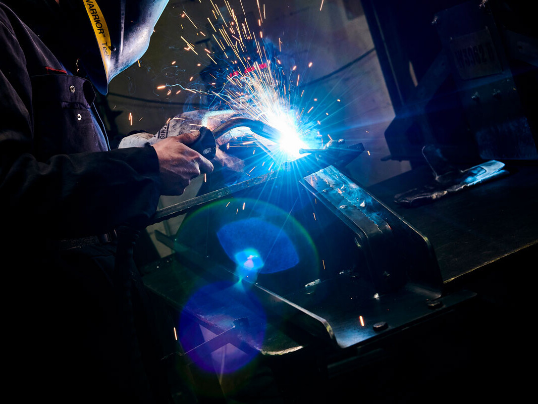
MIG & TIG Welding
Versatile and Capable
Newfield’s welders use both Metal Inert Gas (MIG) and Tungsten Inert Gas (TIG) in a variety of medium to high volume applications, all certified to IATF 16949. We are able to provide Just in Time (JIT) supply, Kanbans and implement Enterprise Resource Planning (ERP).
From support with product design through to cost reductions via a Value Analysis and Value Engineering (VAVE) process, Newfield can work with you from the beginning to hit quality, design and budget targets.
Newfield’s MIG and TIG welding team receive continuous training to maintain their exceptional level of work. While each process has its advantages, our welders maintain a number of skill sets allowing us to easily accommodate a variety of different projects.
We also ensure our welders have the right equipment and have recently invested in new ESAB MIG welding sets. We believe that providing our professionals with the right tools is essential to the standard of work we produce.
Read our handy guide to the differences between MIG and TIG welding.
More Information
MIG Welding
MIG welding is an abbreviation for Metal Inert Gas welding, also known as Gas Metal Arc Welding (GMAW). It is a process developed in the 1940s and is considered semi-automated.
MIG welding requires three things; electricity to produce heat, an electrode to fill the joint, and shielding gas to protect the weld from the air. MIG welding is done using a very small electrode that is fed continuously, while the operator controls the amount of weld being produced.
The equipment used automatically regulates the electrical characteristics of the arc. The only manual controls required of the welder in semi-automatic operation are travel speed, travel direction and gun (torch) positioning.
Given proper equipment settings, the power supply will provide the necessary amperage to melt the electrode at the rate required to maintain the pre-selected arc length (voltage). As the welder squeezes the trigger of the MIG gun, the electricity charges the electrode while the feeder starts feeding the filler wire, creating the weld material. The shielding gas is also fed through the MIG gun nozzle, isolating the weld from the surrounding air and preventing contamination.
Filler metal selection is closely matched to the base material. The filler metal not only conducts electrical current to the arc zone, melting the base metal and electrode, it also adds reinforcement to the completed weld joint.
MIG Welding can be used with a wide variety of metals and base metal thicknesses. Its successful application depends on the appropriate selection of:
- Electrode – composition, diameter and packaging
- Shielding Gas – type (composition), purity and flow rate
- Process Variables – current, voltage, mode of metal transfer and travel speed
- Equipment – power source, welding gun and wire feeder
TIG Welding
Tungsten Inert Gas (TIG), also known as gas tungsten arc welding (GTAW), was originally created by the aircraft industry to weld magnesium in the 1930s and 1940s. It uses the heat generated by an electric arc struck between a non-consumable tungsten electrode and the workpiece. This heat fuses the metal in the joint area and produces a molten weld pool. The arc area is shrouded in an inert gas shield to protect the weld pool and the electrode from oxygen contamination.
The process may be operated autogenously, that is, without filler, or filler may be added by feeding a consumable wire or rod into the established weld pool. TIG produces very high-quality welds across a wide range of materials with thicknesses up to about 8 or 10mm. It is particularly well suited to the welding of sheet material.
One of the greatest advantages of TIG welding is the amount of control it allows. A welder can control heat and amperage with precision using a foot or thumb remote control switch. The TIG gun is thin, which adds to the control a welder can have over the process.
The success of TIG welding hinges on various factors such as the choice of shielding gas, welding wire, tungsten electrode and the user’s technique. The finished product is a sound, slag-free weld that shares the same corrosion resistance properties as the parent metal.
The differences between MIG and TIG welding
MIG and TIG welding both use an electric arc to fuse metal components together. The major difference between MIG and TIG welding is that one process uses a continuously feeding wire (MIG) and the other uses long welding rods that are slowly fed into the weld pool (TIG). TIG is by far the more difficult to learn but both are hard to master.
A MIG welder works by using a continuously feeding spool of welding wire that burns, melts and fuses both the base and parent metals together. You can weld a variety of materials such as mild steel, stainless steel and Aluminium. A range of material thicknesses can be welded from thin gauge sheet metal right up to heavier structural plates. Because it uses filler material, MIG welding often performs better for welding thicker objects, since it doesn’t have to heat the material all the way through to form a bond. Also, the use of filler material makes it slightly easier to control than TIG welding.
TIG welding, on the other hand, can join objects without filler by heating the surfaces to the point where they bond, creating neater welds. It does, however, require a great degree of precision to avoid over-heating the metal, which can cause stress cracks and other issues. TIG welding is more commonly used for thinner gauge materials and is used for things like kitchen sinks and toolboxes. The biggest benefit is that you can use relatively low power and avoid blowing through the metal. It is a much finer and delicate technique that results in a more aesthetic weld.
Resistance Welding
Header goes here
Lorem ipsum dolor sit amet, consectetur adipiscing elit, sed do eiusmod tempor incididunt ut labore et dolore magna aliqua. Tellus at urna condimentum mattis pellentesque. Diam ut venenatis tellus in metus vulputate eu scelerisque. Consequat nisl vel pretium lectus. Nec nam aliquam sem et. Rhoncus urna neque viverra justo nec ultrices dui sapien eget. Donec ac odio tempor orci dapibus. Bibendum neque egestas congue quisque egestas. Pharetra massa massa ultricies mi quis.
Ut porttitor leo a diam sollicitudin. Neque convallis a cras semper auctor neque vitae. Vestibulum rhoncus est pellentesque elit ullamcorper dignissim cras tincidunt lobortis. Purus sit amet luctus venenatis. Sit amet luctus venenatis lectus magna fringilla urna porttitor. Etiam non quam lacus suspendisse faucibus interdum posuere lorem ipsum. In dictum non consectetur a erat nam at lectus urna. Egestas erat imperdiet sed euismod nisi porta. Sit amet cursus sit amet dictum sit. Scelerisque mauris pellentesque pulvinar pellentesque habitant.
Get in touch to learn how Newfield Fabrications can enhance your next project.
Nut Welding
Header goes here
Nut welding describes the projection welding process used to attach threaded nuts to a metal substrate. This is a projection weld because the nuts either have a partial or full ring projection or multiple corner edges cast a projection on the substrate. This is a very common form of welding in the automotive and appliance industries. At Newfield, we offer plate-to-plate welding as well as nut welding, stud welding and bolt welding using the several welding methods at our disposal.
Get in touch to learn how Newfield Fabrications can enhance your next project.
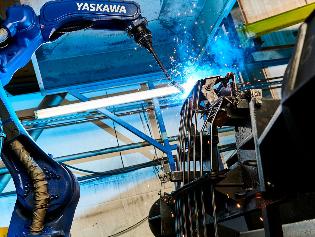
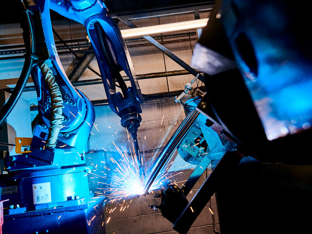
Robotic Welding
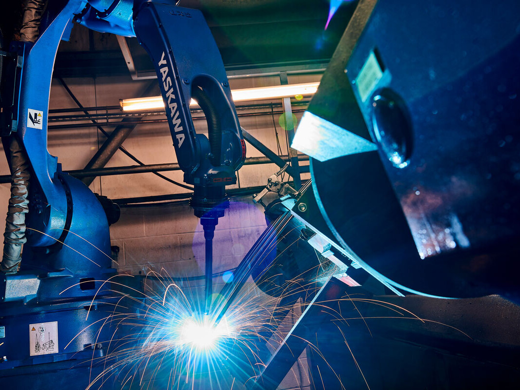
Speed, Reliability and Precision
Robotic welding is a pioneering process that offers increased efficiency through faster and more consistent cycle times. Our six-axis high-performance robots bring speed, reliability and precision to much of our welding work.
We typically use robotic welding for large production volumes and parts required on regular schedules. The process is ideally suited to these applications as the higher cost is mitigated by the volume of output. If quality is paramount, however, then there are significant benefits to using robotic welding for low and medium volume production runs, as well as single items.
We have developed a significant robot welding capacity, with seven robots onsite, two of which were replaced in 2019 in a £150,000 investment.
Our robots can handle metal fabrications up to 5 tonnes and workpieces 8m long and 2.4m in diameter. All of our robots feature two workstations, allowing one piece to be set up while another is being welded, improving efficiency for large assemblies.
More Information
1. Increase in Productivity
Robot welding is often a fast process because it can operate continuously, withstanding a greater arc on-time and moving quickly between weld joint positions. A robotic welding system can provide substantial increases in output.
2. Consistent and Repeatability
Manual welding requires a high level of skill and concentration to achieve reliable consistency. A robotic welder can continue to perform precisely the same weld cycle continuously, 24 hours a day, seven days a week. This is particularly important for complex welds with restricted access, where a robot is able to maintain much greater control.
3. Flexibility
Our robots can be programmed with a vast number of parts, enabling us to simply swap the jig on the robot bed, load the materials and begin the programme.
4. Safety
Robotic welding can improve safety through the reduction of handling and operating within an enclosed cell.
5. Quality
A robotic welder can achieve superior quality by ensuring the correct welding angle, speed, and distance, with repeatable accuracy of ±0.04mm. Ensuring that every welding joint is consistently produced to a very high standard significantly reduces the risk of costly rework.
6. Labour
Robotic welding systems are ideal for alleviating workload during busy periods. These systems allow less experienced welders to consistently perform high-quality welds. Our robot operators are all highly experienced and understand the distinct advantages of using our robotic systems.
7. Reduce Consumables
The consistency of robotic welding allows us to optimise the welding processes, reducing costs associated with welding consumables.
8. Reduced Production Costs
Through improvements in quality, consistency and productivity, a robotic welding system can deliver parts at a reduced cost. Further savings can be made through reduced energy consumption and consumable costs, alongside decreased labour and insurance costs.
9. Reduction in Weld Distortion
Distortion in a weld is due to the expansion and contraction of the weld metal and the adjacent base metal during the heating and cooling cycle of the welding process. A manual process is less repeatable – meaning two qualified welders will have slightly different techniques. If there is a difference in the heat applied, it can create distortions. Robotic welding is both accurate and repeatable, reducing the risk of differences between welds and ensuring consistency.
10. Increased Competitive Advantage
Implementing a robotic welding solution can set companies apart from the competition, allowing for faster completion and delivery of products whilst ensuring consistent quality.
Fabrication
Industry-leading Metal Fabrication
We have 60 years of experience as an industry-leading fabrication company. From construction equipment to rail, automotive, nuclear and recycling, our expert team is relied upon in almost every sector. We offer a range of quality metal fabrication and welding services in line with IATF 16949 and ISO 9001:2015 standards.
Continuous Investment
Training and technology has placed us at the forefront of the metal fabrication industry and established our reputation as a preferred manufacturing partner for many blue chip clients. Our fabrications meet stringent internal quality control, and we are accredited to IATF 16949 – the world’s foremost quality standard for the automotive industry.
MIG, TIG or Robotic?
We offer a range of metal fabrication and welding services based on our team’s extensive experience and modern equipment. Our highly qualified and experienced operators work in advanced, purpose-built welding bays and can undertake both large and small-scale projects. They are capable of many additional assembly processes, including spot welding, projection welding and nut welding. We can also provide finishing operations, using grinding and sanding techniques to ensure that your parts have the desired surface finish.
Cost-effective Processes
Newfield’s dedicated engineering team are able to select the most appropriate method to produce the part you require and are trained to follow the Value Analysis Value Engineering (VAVE) process. The technique allows them to significantly reduce the number of components in complex fabrications or minimise the number of required operations, using advanced bending to create a part without welding enables Newfield to offer the product at a more competitive cost.
Cost-effective Manufacturing
Our expert welders are also specialists in one-offs, prototypes and low-volume products, with a capacity for large fabrications up to 10 tonnes. For cost-effective manufacture, we minimise tooling and fixturing, instead relying on the experience and knowledge of our skilled welders to complete the parts to Newfield’s demanding quality standards. If the part is highly complex, then it may be necessary to use a fixture. Likewise, we are open to using a fixture if specifically requested by the customer or fabricating hand-built projects without one.
More Information
At Newfield, our investment in leading-edge equipment and our team’s dedication to quality provide exceptional versatility. Our welder’s skills are continually refined, and they can perform a variety of resistance welding jobs including spot welding, projection welding and nut welding.
Spot welding
Resistance spot welding (RSW) is a process in which contacting metal surface points are joined by the heat from an electric current. Workpieces are held together by two shaped copper alloy electrodes. The electrodes concentrate welding current into a small “spot” melting the metal to form a weld. At Newfield, we utilise pre-determined programmes that take into consideration material thickness, current, pressure and the duration of the process.
Projection welding
Projection welding is a modification of spot welding. In this process, the weld is localized by means of raised sections, or projections, on one or both workpieces. Heat is concentrated at the projections, which permits the welding of heavier sections or closely spaced welds. The projections can also serve as a means of positioning the workpieces. Projection welding is often used to weld studs, nuts, and other threaded machine parts to the metal plate. It is also frequently used to join crossed wires and bars. Multiple projection welds can be arranged by suitable designing and jigging.
Nut welding
Nut welding describes the projection welding process used to attach threaded nuts to a metal substrate. This is a projection weld because the nuts either have a partial or full ring projection or multiple corner edges cast a projection on the substrate. This is a very common form of welding in the automotive and appliance industries. At Newfield, we offer plate-to-plate welding as well as nut welding, stud welding and bolt welding using the several welding methods at our disposal.
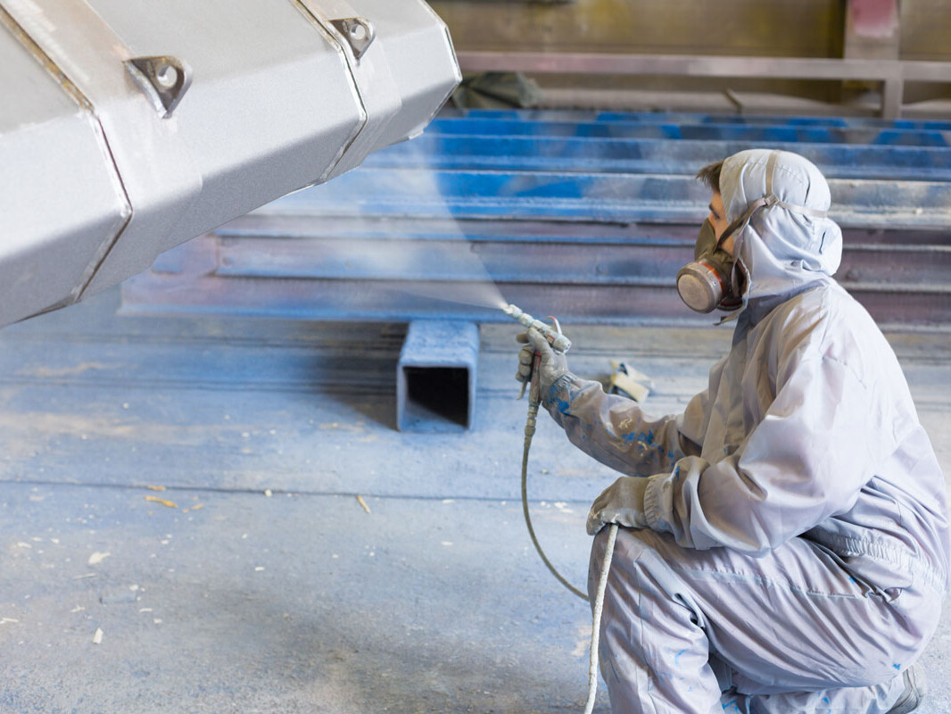
Wet Spray
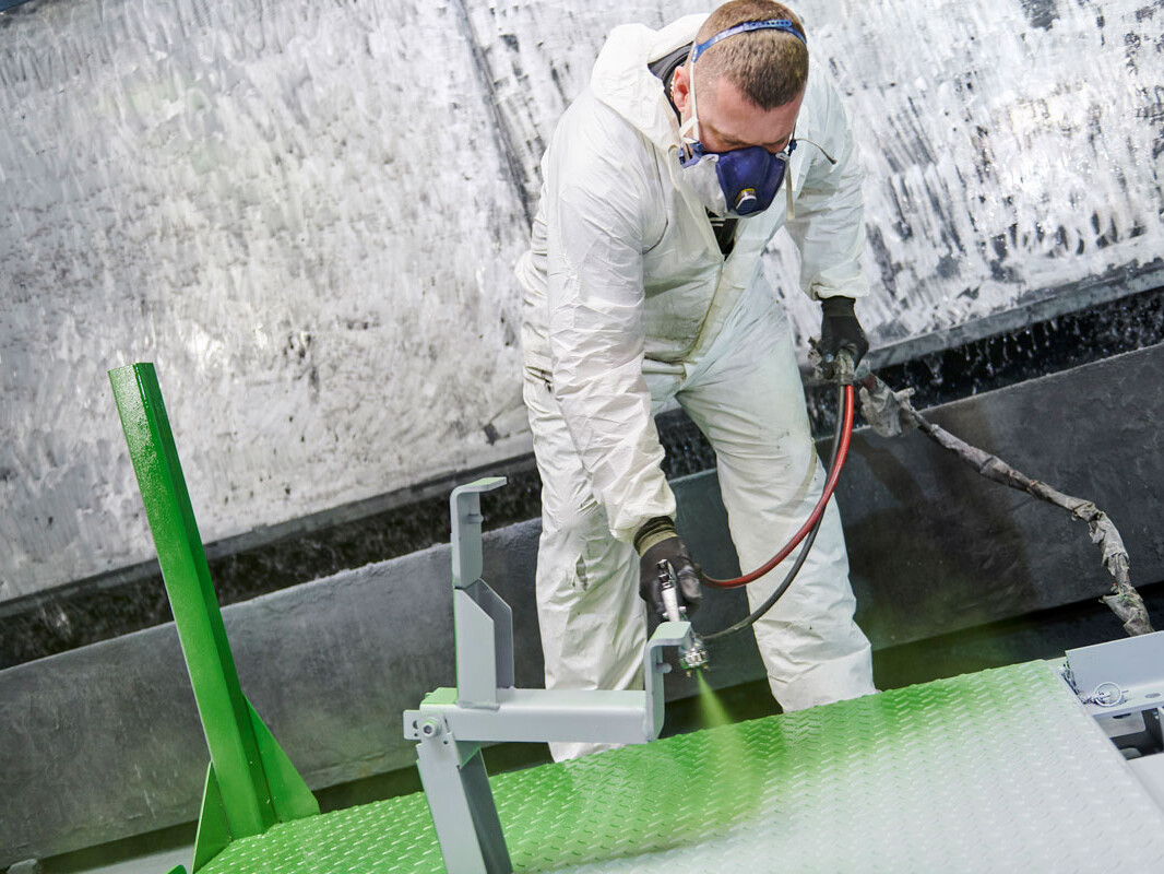
Wet Spray Process
Wet paint is the ‘traditional’ process of applying liquid paint to a metal product for finishing. The part is first shot-blasted, with small abrasive particles propelled toward the surface to provide a thoroughly clean substrate for the wet painting. Once the surface has been prepared, the liquid paint is applied using a spray, pump or pressurised vessel to deliver it evenly. It is applied until the product is evenly coated with the desired thickness, usually 15-20µm.
Our wet spray meets the ACT (Accelerated Corrosion Test) ASTMD1654 standards and has passed 240hrs salt spray.
Benefits of wet spray:
- Wet spray painting is particularly useful for large, heavy or awkwardly shaped objects that cannot be hung for powder coating.
- The process is very efficient for large components.
- It is a cost-effective finish, significantly more economical than some alternatives – particularly for low production runs.
- Colour selection is practically infinite, providing the opportunity to match branding or aesthetic requirements. Toning is very precise, making colour matching a possibility.
- It can be applied to a range of materials and is ideally suited to heat-sensitive parts that cannot be powder coated.
- The paint applied is a much thinner coating than other processes, which may benefit lightweight or precision parts.
- Wet spray painting allows you to air-dry or bake your product for finishing.
- It is possible to achieve a variety of gloss levels and paint textures, applying them consistently for a high-quality finish across the entire surface area.
Limitations of wet spray:
- The process itself is not as efficient; powder-coating typically has a transfer efficiency of 60-70%, whereas wet spray is approximately 30-35%.
- It is less environmentally friendly due to the chemicals in the paint.
- The thinner coat of wet spray paint means that it is not as durable as powder coating.
- It may require multiple coats to achieve an even surface finish.
Powder Coating
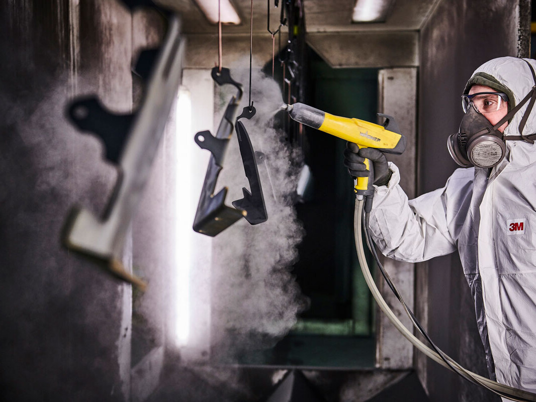
Protection and High-quality Finish
For many of our customers, powder coating is an essential part of their manufacture process, providing both elemental protection and a high-quality aesthetic finish. Newfield offers a diverse selection of powder coating colours at its purpose-built site less than 400 metres from our main facility. We conduct regular quality checks to ensure that all powder coating services are carried out to customer specifications and only use powders supplied by recognised manufacturers. Conforming with the rest of our facility, full traceability and compliance with IATF 16949 and ISO 9001 are maintained throughout the metal powder-coating process. Our metal powder coating meets the ACT (Accelerated Corrosion Test) ASTMD1654 standards and have passed 1008hrs salt spray.
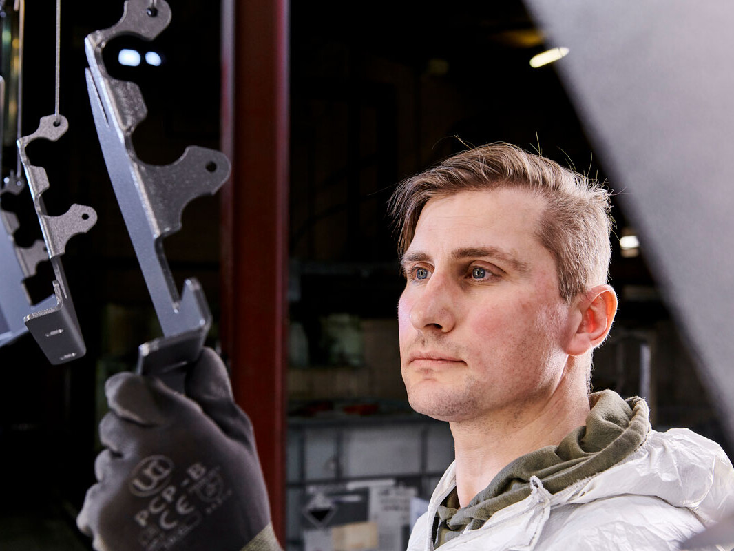
Once the parts have completed and passed their visual inspections, they will either be packaged to customer specifications or transported back to our main site for additional engineering operations, dependent on the specifications of the part.
Benefits of powder coating:
- Powder coating provides a long-lasting, economical, and durable finish with a range of colour options available.
- Powder-coated surfaces are more resistant against scratches, chipping, wear, and fading than other types of finishes.
- It is more environmentally friendly as it does not use solvents and produces few volatile organic compounds.
- As the powder is very fine, it is possible to apply thicker coats without running or clogging. It is typically a one-coat finish.
- The powder coating process includes curing in an oven, creating a protective layer that is much harder than conventional liquid paint.
- Powder coating creates a very even surface finish, vertically and horizontally, because it is sprayed and heated without drips or application traces.
Limitations of powder coating:
- It is harder to achieve a thin finish with metal powder coating.
- The time taken for a colour change is considerably higher for powder coating than wet spray painting, but this includes the time required to perform the quality checks necessary to maintain a high standard of finish.
More Information
What is Powder Coating?
Powder coating is a dry finishing process that has become extremely popular since its introduction in the 1960s, with the global powder coating market expected to reach £9.66bn by 2020. Powder Coating represents over 15% of the total industrial finishing market and is used on a wide array of products.
It is growing popularity thanks to its high-quality, corrosion-resistant finish and aesthetic appearance.
The main difference between a conventional liquid paint and a powder coating is that the powder coating does not require a solvent to keep the binder and filler parts in a liquid suspension.
Intricate fabricated metal shapes can be powder coated evenly and without sagging, allowing for much thicker coats when compared to paint finishes. Powder Coating can be used for both functional and decorative finishes, with an almost limitless number of colours and textures available.
How powder coating works
Powder coatings are based on polymer resin systems, combined with curatives, pigments, levelling agents, flow modifiers, and other additives. These ingredients are melted, cooled, and ground into a uniform powder similar to baking flour. A process called Electrostatic Spray Deposition (ESD) is typically used to achieve the application of the powder coating to a metal substrate. This application method uses a spray gun to apply an electrostatic charge to the powder particles, each of which is then attracted to the grounded part.
After application of the powder coating, the parts enter a curing oven where, with the addition of heat, the coating chemically reacts to produce long molecular chains, resulting in high cross-link density. These molecular chains are very resistant to breakdown and give powder coating its mechanical properties. This type of application is the most common method of applying powders.
Powder coating is based on the principle that objects with opposite electric charges (positive and negative) attract one another. The powder particles are negatively charged after passing through the special spray gun, making them attracted to the earthed part achieving high levels of adhesion and consistency.
Most conducting or thermally stable materials are suitable for powder coating, metals are particularly good due to their high electrical and thermal conductivity. Even complex metal components can be powder coated evenly, with excellent adhesion.
The durability of powder coating
Powder coating is a high-quality finish found on thousands of products you come in contact with each day. It protects the roughest, toughest machinery as well as the household items you depend on daily. It provides a more durable finish than liquid paints can offer, while still providing an attractive finish. It is a tough coating that can resist impact, moisture, chemicals, ultraviolet light, and other extreme weather conditions, reducing the likelihood of scratches, chipping, abrasions, corrosion, fading, and other wear issues.
Pre-treatment process for powder coating
Unlike Iron-Phosphate treatments, Zinc-Phosphate is unable to clean and coat simultaneously and so our 8-stage Zinc-Phosphate process includes cleaning, rinsing and conditioning stages. The reason that we use Zinc-Phosphating over Iron is that Zinc-Phosphate coatings are extremely adherent, they provide a uniform coating with improved coating adhesion properties, better coating in recessed areas and better corrosion resistance and have been widely used in the automotive sector for many years.
Prior to parts undergoing the Powder Coating process, they must first be pre-treated and at Newfield, we operate a Zinc Phosphate pre-treatment process which is comprised of 8 quality-controlled stages:
Stage 1 – Clean
This stage of the pre-treatment process ensures that the parts are free from any residual surface residue such as rust preventative oils and lubricants, machining oils, rolling mill or heat scale, metallic fines and laser scale.
Stage 2 – Rinse
This stage ensures that the part is now free from any excess chemicals from the previous stage and requires the basket to be submerged in constantly agitated clean water for 1 minute.
Stage 3 – Acid
This stage removes any imperfections around the edges of the parts caused by the laser cutting process and ensures any remaining surface contaminants are removed. This process is stringently controlled and monitored through our pre-treatment quality checks which themselves are audited weekly to verify all results.
Stage 4 – Rinse
This stage ensures that the part is now free from any excess chemicals from the previous stage and requires the basket to be submerged in constantly agitated clean water for 1 minute.
Stage 5 – Activate
This stage is used to provide a very uniform micro-crystalline coating which provides maximum effectiveness in the Zinc Phosphate stage.
Stage 6 – Phosphate
This stage involves a chemical reaction between the substrate and the Zinc-Phosphate and is used to provide a uniform crystal layer which the powder then adheres to during the Powder Coating process.
Stage 7 – Rinse
This stage ensures that the part is now free from any excess chemicals from the previous stage and requires the basket to be submerged in constantly agitated clean water for 1 minute.
Stage 8 – Dry
This stage requires the basket to be contained within an oven for 20-30 minutes (dependent on the properties of the part in question) to ensure the part is free from any liquids and that the part is dry and ready to be moved to our paint-line.
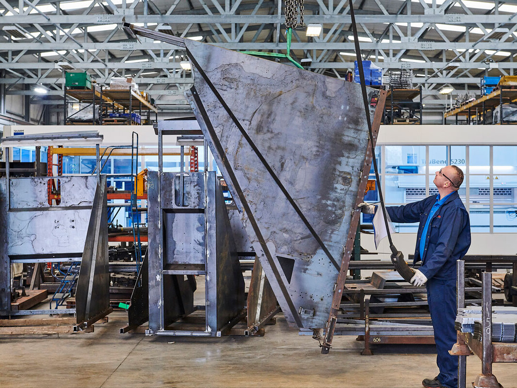
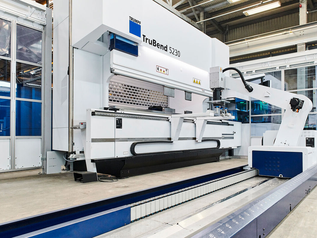
CNC Press Braking
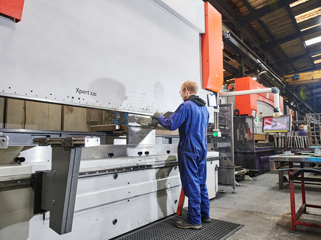
Metal Folding Capacity
We understand the importance of ongoing investment in the latest technologies, equipment and training to the high standard of our output quality and IATF 16949 certification. Our programme of continuous improvement means that our metal bending and folding capacity can meet the most demanding metal fabrication contracts, large or small, simple or complex.
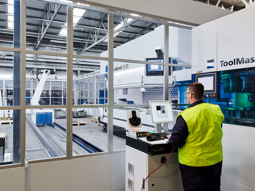
Newfield’s modern metal fabrication facility includes 10 press brakes and a new, fully automated forming cell. It is comprised of a 230T press, 150kg bendmaster and ToolMaster. The cell can produce unmanned parts weighing in excess of 100kg and complete changeovers for multiple product runs. It also uses the ACB system, which monitors and corrects metal forming during manufacture to remove the need for rework.
Our extensive metal folding capacity includes Trumpf, Amada and Bystronic machines, with a press range from 50 to 400 tonnes. Press brakes can often handle a broader range of material thicknesses than panel benders, allowing us to maintain versatility within the market.
The use of semi-automated measurement systems reduces manufacture processing time, improving site efficiency. This is also supported with offline programming to minimise downtime on new product introductions.
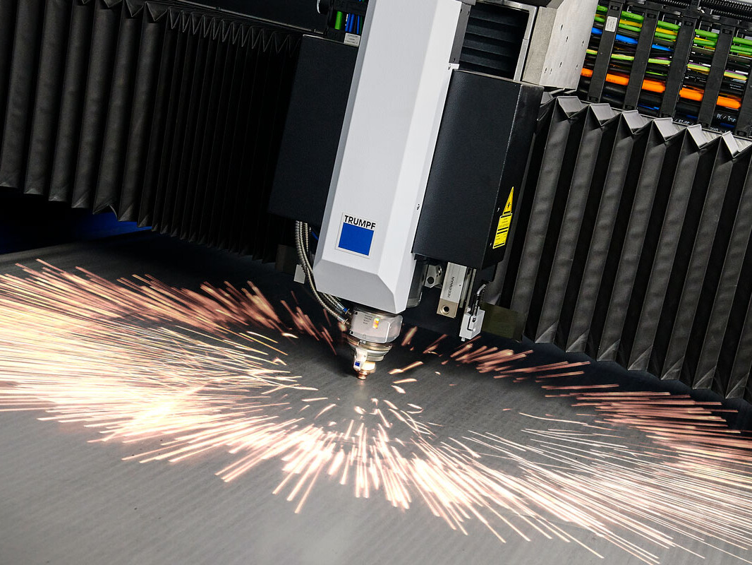
Laser Cutting
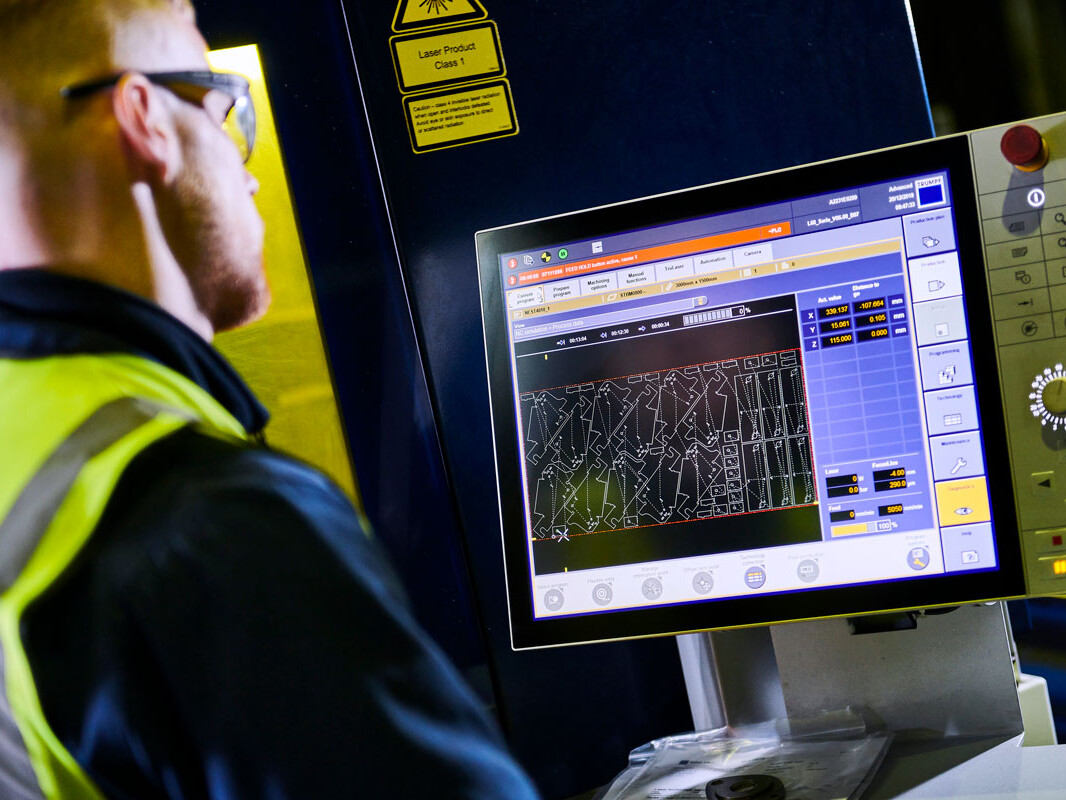
Laser Cutting Service
We continually invest in advanced equipment and staff training to ensure that our processes deliver to customer requirements and IATF 16949 standard. In 2019, Newfield invested over £1.3m in its laser cutting department, greatly enhancing its capacity and capabilities. Our laser operators receive their initial training directly from Trumpf and frequently undertake training to build on their extensive experience, honing their skills and knowledge of laser cutting processes and technologies.
Latest Technology
Our machines offer supreme flexibility, handling profiles from the simplest components to shapes of almost limitless complexity. This versatility extends to both pre-production samples and production batches. CNC laser cutting also leaves clean edges and a high-quality surface finish, requiring less cleaning or additional surface work. At Newfield, we use Nitrogen cutting to eliminate oxidisation at the edges, thereby reducing the required pre-treatment time.
Technical Data

Laser Data


With three Trumpf laser cutting machines, each with a 3 x 1.5-metre sheet metal capacity and automated loading and unloading systems, we have the capacity to meet your needs.
- 5KW 5030 highly specified CO2 and nitrogen machine with semi-automated loading capabilities.
- 8KW 5030 Fibre laser equipped with Liftmaster for semi-automated loading and unloading and the capacity to cut using Oxygen or Nitrogen. We also utilise Trumpf’s Highspeed Eco system upgrade for thicknesses from 4-8mm. In some cases, Highspeed Eco is capable of doubling the machine’s throughput.
- 10KW 5030 Fibre laser which boasts Smart Beam Control (SBC), Active Speed Control (ASC) and a fully automated tower system for loading and unloading.
Find out more about our 10kW Trumpf TruLaser 5030 here
Newfield uses an advanced CADCAM system, Boost, to produce the CNC code which enables components to be programmed quickly and accurately, ensuring there are no delays leading up to, or during, production. It also merges all the steps needed to generate sheet metal manufacturing programs into a single system, including everything from part design and data import to nesting and even writing CNC programs for cutting, punching and bending.
More Information
Laser cutting technology offers supreme flexibility and is capable of creating simple profiles through to highly complex shapes. It uses a high-energy infra-red laser beam and a focusing lens to concentrate energy to a fine point. This causes rapid localised melting and partial vaporisation of the material. Nitrogen gas is directed through a nozzle and blasted at the surface, removing excess molten material and prevent oxidisation. The laser can be used to cut out patterns and shapes from flat sheet metal or piping.
On a precision laser cutter, the head moves over the sheet metal plate in a precise prearranged pattern, maintaining a highly accurate distance between the cutting head and the metal plate. Compared to mechanical cutting, lasers offer better material management, lower energy consumption and more precise and cleaner edges.
Lasers can be used on a variety of materials but are ideally suited to large sheet metal plates made of mild steel, stainless steel and aluminium. It is a very accurate process and causes minimal heat damage to the material. The accuracy, quality and consistency of the cut mean that lasers can be used to cut intricate shapes, elaborate patterns and small holes.
What is Kerf?
The laser burns away a portion of material when it cuts through. This is known as the laser kerf and ranges from 0.08mm – 1mm depending on the material type and as well as other factors. Any areas in your design where cut-lines are closer than 0.5mm together could burn away entirely. Any details narrower than 1mm are likely to be very fragile and in some cases can cause the material to warp whilst cutting. As a benchmark, it is recommended that minimum cut widths be no smaller than the corresponding thickness of the material.
For example, if cutting from 3mm mild steel, it’s best not to allow any widths less than 3mm. We can go smaller, but this can make your pieces very fragile and therefore susceptible to defect during the manufacturing process. Our engineering team will advise if your drawing has cutting tolerances that are too small and will work with you to resolve the issue.
Kerf is determined by material properties and thickness. But other factors also have an impact on how much the laser removes. The focal length of the lens, as well as pressure of the compressed air, can both have an impact. Kerf widths can vary even on the same material sheet, whether cutting a straight line or a curve line or from laser cutting in the X or Y-Axis. The manufacturing tolerance of the material can also impact the kerf.
There are many other parameters that also affect cut quality, but when all are controlled properly, laser cutting is a stable, reliable, and very accurate process.
TruTops Boost
At Newfield, we use TruTops Boost software to help generate sheet metal manufacturing programs. It aides with everything from part design and data import to nesting and writing cutting programs. The software makes sheet metal processing quicker and more intuitive, increasing productivity while ensuring high-quality output.
With TruTops Boost, designing and programming for sheet metal processing are made quicker and more intuitive than ever before. It provides our engineers with the latest version of all current job orders, displaying their status within the current process step. It also immediately recognises when a design specification has been changed, automatically adjusting the upline or downline steps and notifying the operator if there is a need to intervene. The software also considers all available technology when processing part data, ensuring that the best methodology is implemented.
Thanks to Newfield’s recent investment in a new TruBend 230S cell, this software is also being used by our Press Department.
Productive processing, smooth processes
Our TruLaser 5030 fibre is capable of both high processing speed and consistent, high part quality – even for complex contours. It achieves excelled feed rates thanks to its advanced solid-state laser. Newfield’s 5030 uses a suite of assistant systems to accelerate the machining process, increasing productivity and reliability. Operator involvement is minimal with numerous autonomous capabilities, increasing uptime. Listed below are some key features of Newfield’s 10KW TruLaser 5030 fibre.
- High machine dynamics: the 5030 can effortlessly handle complex contours in both thin and thick sheets. It has been designed to operate at maximum capacity and high feed rates without compromising quality.
- Process reliability: even in fully-automated operation, the 5030’s Smart Nozzle Automation ensures that the nozzle and lens are kept in excellent cutting condition. The CoolLine function allows the user to perform delicate cutting operations in thick steel by cooling the workpiece. This also enables new and complex geometries as well as more efficient sheet configuration and reliable processing of thick material.
- Extremely fast: The 5030’s Highspeed Eco mode allows for up to 100% greater productivity while a patented nozzle reduces nitrogen gas consumption by up to 70%. This process is ideal for structural steel and stainless-steel sheets with no reduction in quality.
- Part quality: for the highest possible part quality, the 5030 uses BrightLine fibre – a combination of special optics and flow-optimised nozzles.
- Semi-autonomous operation: Thanks to the 5030’s Active Speed Control, the system can see through the nozzle and into the kerf, monitoring the cutting process and regulating feed rate automatically. Active Speed Control also works with variations in material thickness and surface quality, such as rust or traces of coating. It prevents disruption of the cutting process thereby reducing the number of rejected parts significantly.
Stainless Steel and Non-Ferrous Metal
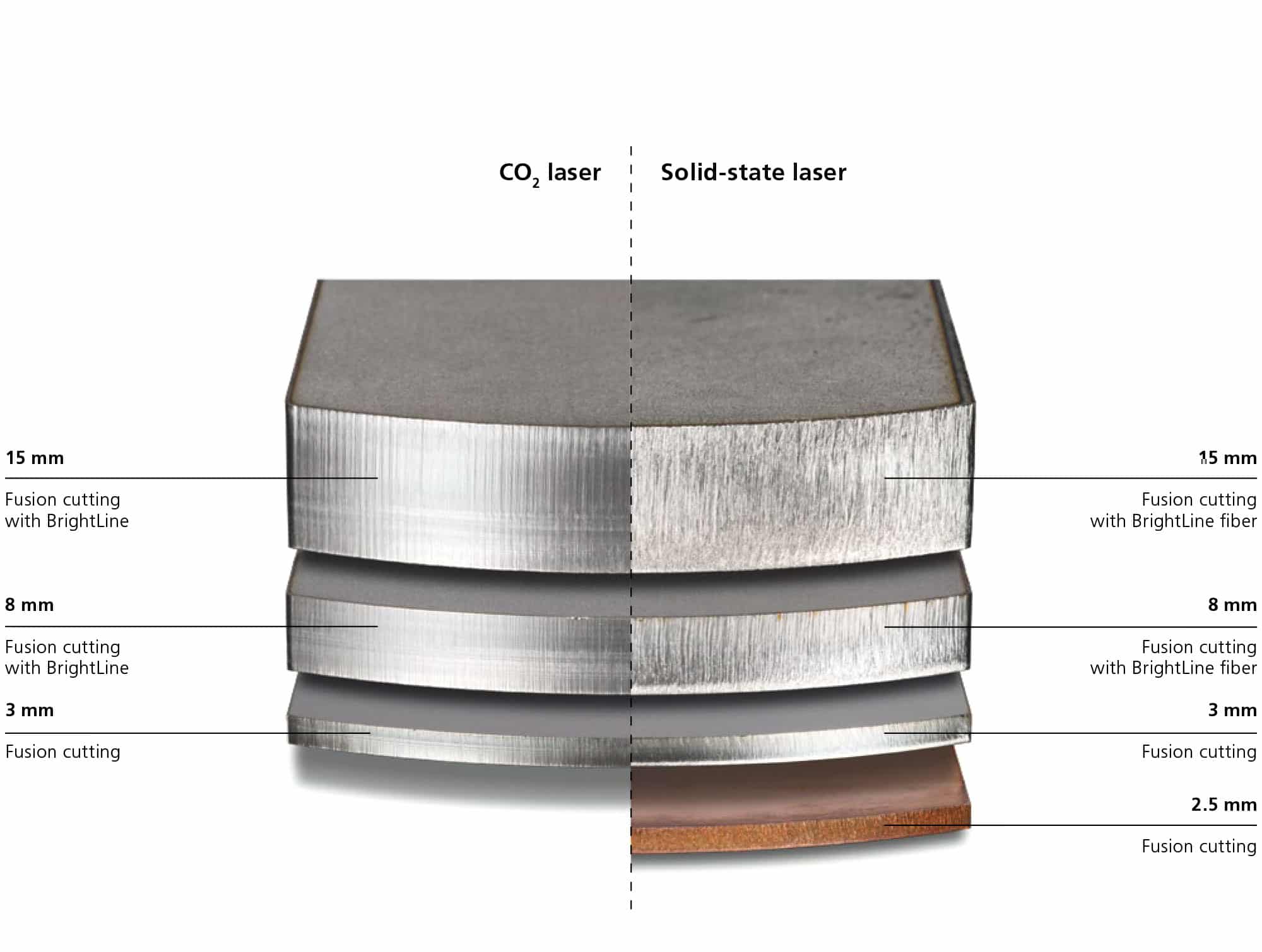
The Result:
CO2 Laser:
Exceptional part quality with extremely smooth and partly reflective edges – with BrightLine for thick sheet metal, and without BrightLine for thin sheet metal. Virtually no burr formation.
Solid-State Laser:
Excellent part quality with thin sheet metal, assisted by BrightLine fiber with thicker sheet metal to ensure a consistent sectional view.
Structural Steel
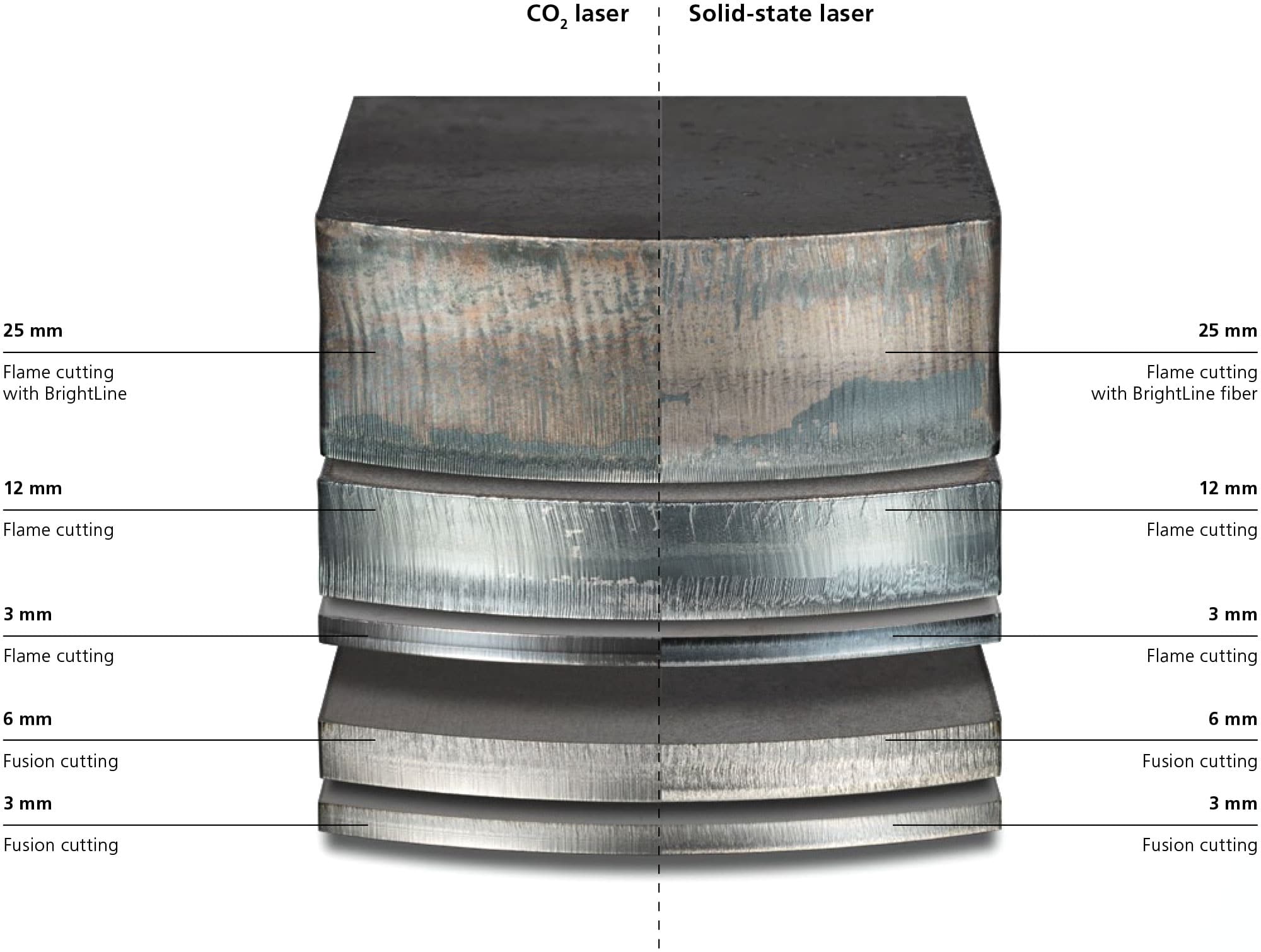
The Result:
CO2 Laser:
When carrying out flame cutting (with oxygen), both laser beam sources achieve the same level of quality. When carrying out fusion cutting (with nitrogen), the CO2 laser outperforms the solid-state laser.
Solid-State Laser:
A slight burr forms when carrying out fusion cutting.
TruLaser Series 5000

Maximum Dynamics
The productive machines in the TruLaser Series 5000 can effortlessly handle both thin and thick sheets. With the TruDisk 10001 and highly dynamic drives, they enable highly productive and reliable manufacturing across the entire range of sheet thicknesses. The machines in this range are designed for maximum capacity and are able to convert these high feed rates into sheet throughput.
Producing with Process Reliability
Ensuring that the nozzle and lens are in the best possible condition is an important prerequisite for achieving reliable processes and high part quality. Smart Nozzle Automation combines intelligent functions that ensure just that – even in fully automatic operation. With the CoolLine function, you can perform delicate cutting operations, even in thick structural steel. This function cools the workpiece during cutting and enables new geometries, more efficient sheet configuration, and reliable processing of thick structural steel.
Extremely Fast
The Highspeed Eco cutting process enables you to get even better performance from your laser machine. When carrying out nitrogen cutting, this method enables you to nearly double your feed rate and sheet throughput when processing medium and thick structural steel and stainless steel sheets, without any reduction in quality: Highspeed Eco even prevents burr formation on contours with sharp edges.
Top Part Quality
BrightLine fiber combines special optics with flow-optimized BrightLine nozzles and the switchable 2-in-1 cable. The result of this is that you achieve maximum part quality. The high- quality cut edges ensure that your parts do not get caught during removal, saving you a great deal of time.
Unrivaled Economical
With an efficiency rate of over 30%, the energy consumption of a TruDisk solid-state laser is exceptional. The Highspeed Eco function helps you to achieve cutting gas savings of up to 70% – thanks to a patented nozzle design.