Home 2
Metal Fabrication
For the last 60 years, our metal fabrications have been used around the world. Our dedication to quality has seen the business successfully expand into a number of highly demanding industries – from the automotive and MoD to nuclear and off-highway.
We are driven by the need to continuously improve. Through significant investment in staff training and leading-edge equipment, we maintain a high level of expertise and experience within the company. Newfield Fabrications remains at the forefront of the UK fabrication industry and a trusted manufacturing partner to companies worldwide.
Since 2009, Newfield have continually provided quality assemblies that have helped our company grow into a diverse range of new sectors. We have no hesitation in recommending their skilled craftsmanship and attentive customer service.
Since 2009, Newfield have continually provided quality assemblies that have helped our company grow into a diverse range of new sectors. We have no hesitation in recommending their skilled craftsmanship and attentive customer service.
Name here, Position here, Company here


Latest News
Nothing found.
Case Studies

Case study one title goes here
Lorem ipsum dolor sit amet, consectetur adipiscing elit, sed do eiusmod tempor incididunt ut labore…
Case study two title goes here
Lorem ipsum dolor sit amet, consectetur adipiscing elit, sed do eiusmod tempor incididunt ut labore…
Case study three title goes here
Lorem ipsum dolor sit amet, consectetur adipiscing elit, sed do eiusmod tempor incididunt ut labore…
Case study four title goes here
Lorem ipsum dolor sit amet, consectetur adipiscing elit, sed do eiusmod tempor incididunt ut labore…
Case study five title goes here
Lorem ipsum dolor sit amet, consectetur adipiscing elit, sed do eiusmod tempor incididunt ut labore…
Case study six title goes here
Lorem ipsum dolor sit amet, consectetur adipiscing elit, sed do eiusmod tempor incididunt ut labore…
Terms & Conditions of Sale
Terms & Conditions of Sale
Definition
The following terms used in these Terms and Conditions of Sale will mean as follows:
‘Company’
Newfield Fabrications Co. Limited.
‘Customer’
The Company, Firm or Person purchasing goods or services from the Company.
‘Contract’
The Sale taking place between the Company and the Customer.
‘Goods’
Any product or service supplied by the Company.
General
All orders accepted by the Company for the supply of goods and all goods subsequently supplied, will be accepted and supplied in accordance with the Terms and Conditions of Sale.
Quotations/Prices
All quotations are made and all orders are accepted subject to these Terms and Conditions of Sale and no addition thereto or variation therein shall be made unless agreed in writing by the parties. These Terms and Conditions shall prevail over any terms and conditions contained in the Customer’s order.
The Company reserves the right to refuse the Customers acceptance of a quotation unless such quotation is stated to be open for a specific period and is not withdrawn within such period. All prices which the company quotes are based on materials, labour, transport and other cost prevailing at the date of the Contract and are subject to variation without notice. Orders can only be accepted on the understanding that supplies will be invoiced at the prices ruling at the date of despatch.
Divisibility Clause
This Contract is divisible. Each delivery made hereunder shall be deemed to arise from a separate Contract and shall be invoiced separately; any invoice for a delivery shall be payable in full in accordance with the terms of payment provided for herein, without reference to and notwithstanding any defect of default in delivery of any other instalment.
Delivery
Where delivery of goods takes place by the Company’s own vehicle, no carriage charge will occur unless by prior arrangement.
Where delivery takes place by other means the Company reserves the right to charge the Customer accordingly.
Returns/Rejection of Goods
Unless otherwise agreed, goods rejected by the Customer as not complying with the contract must be so rejected within 10 days of receipt by the Customer.
Loss or Damage in Transit
No responsibility will be accepted for any discrepancy in the quantity of goods or damage thereto unless notified to the Company in writing within 10 days of receipt by the Customer.
Risk
The risk in all goods the subject on any Contract passes to the Customer at the time the Contract is made.
Ownership of Goods
All goods supplied by the Company shall remain the sole and absolute property of the Company as legal and equitable owner until such time as the Customer shall have paid to the Company the price therefore together with the price of any other goods the subject of a Contract between the Company and the Customer. The Company may enter upon any premises where the goods are stored to repossess the same and until such time as the Customer becomes the owner of the goods the Customer will store them at the Customer’s premises separately from any other goods and in the manner which makes them identifiable as goods of the Company.
The Customer shall be licensed to agree to sell or sell the goods supplied but on the express condition that the whole of the proceeds of sale are held in trust for the Company and not paid into any overdrawn banking account.
Payment
Unless otherwise agreed in writing, payment in full is due in respect of any goods delivered by not later than one month from the date of the invoice.whilst having access to up to their status at any time.
Enquire
Make an Enquiry
Please fill in our enquiry form with your details and requirements and one of our sales engineers will respond shortly.
Programming

Heading goes here
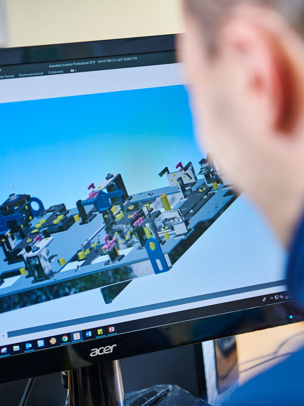
Using the latest software, our Engineering team are able to design the parts as well as create Standard Operating Procedures (SOPs) to show the operators how to complete each operation. We have also adapted this software for use on our non-automated machines, making tool selection easier and improving accuracy. These SOPs are included in information packs that accompany each part around the factory.
Learn more about our design considerations for bending work.
More Information
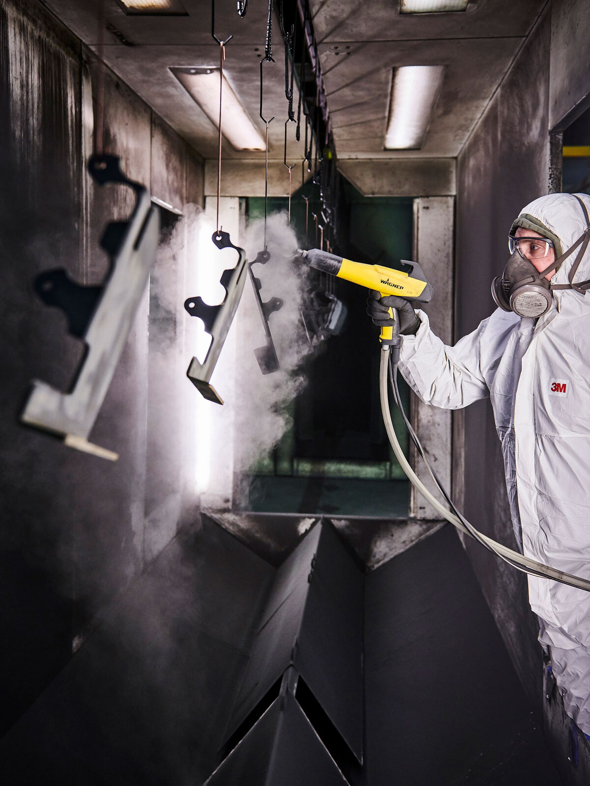
Here at Newfield, we utilise a process known as ‘air bending’ that uses the minimum amount of force possible. This maximises the capability of the press brake while reducing tooling wear.
Bend Radius (Inside Bend Radius)
With air bending, the inside radius is predominantly determined by the die opening (also referred to as V-width). In order to reduce the required force, a larger V-width must be used. Generally, the minimum inside radius is equivalent to the thickness of the material. Because dies are manufactured in specific sizes, generous tolerances should be allowed – up to ± 30%.
Minimum Flange Length
It is recommended that the minimum flange length should be at least four times the material thickness. The V-width of the press brake determines how small the flanges can be. Smaller flanges than this are only possible with additional work, such as forming a larger flange and then machining it down, adding expense. Our team of design engineers will thoroughly analyse the manufacture of a part, including possible tooling, to ensure costs are minimised and the part meets all requirements.
Bend Relief
If a bend is too close to an adjacent edge, the material is likely to tear. To prevent this, the relief length should be greater than the radius of the bend. The width of the relief should also be the equivalent of the material thickness, at least. There are several advantages to a larger bend relief, including ease of component alignment, prevention of crack propagation and the reduction of setup and running costs.
Forming Near Holes
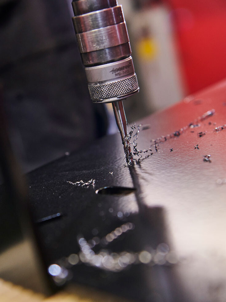
It is recommended that holes are positioned away from bends to avoid distortion. As the material is bent, the hole will deform from its original size and shape, likely preventing it from performing its intended function. Any holes located close to a bend must be created after bending as part of a secondary machining operation. To avoid the associated expenses, any holes or slot edges should be positioned so that they are clear of the die opening when the bend is formed. Generally, this means holes or slot edges must be offset around 3-4 times the material thickness from the bend line.
Bend Edge Distortion
Distortion can be created at the edge of a bend as material thickness increases and the bend radius decreases, this is part of the bending process. If this is unacceptable, then the component can be relieved.
Dimensions
Our engineering team dimensions parts in a single direction, where possible. Due to the sequential nature of the forming process, and the fact that dimensional variations are introduced by each bend, dimensioning in a single direction helps to control tolerance accumulation.
Our Engineering team not only rely on their personal expertise but also “shop-floor” knowledge, collaborating to determine the best tool selection and critically comparing this with what has been recommended by the software. This ensures that the most appropriate tool is used every time and that the parts meet the dimensional tolerances requested by the customer.
If a blank development is required, it should be marked up as ‘For Information Only’. Developments provided by third parties are often created without consideration for the actual press brake tools used during production. To guarantee the desired quality, it may be necessary to generate a blank development to suit the tooling, ensuring that the formed component matches the requirements.
Get in touch to learn how Newfield Fabrications can enhance your next project.
Automated Forming
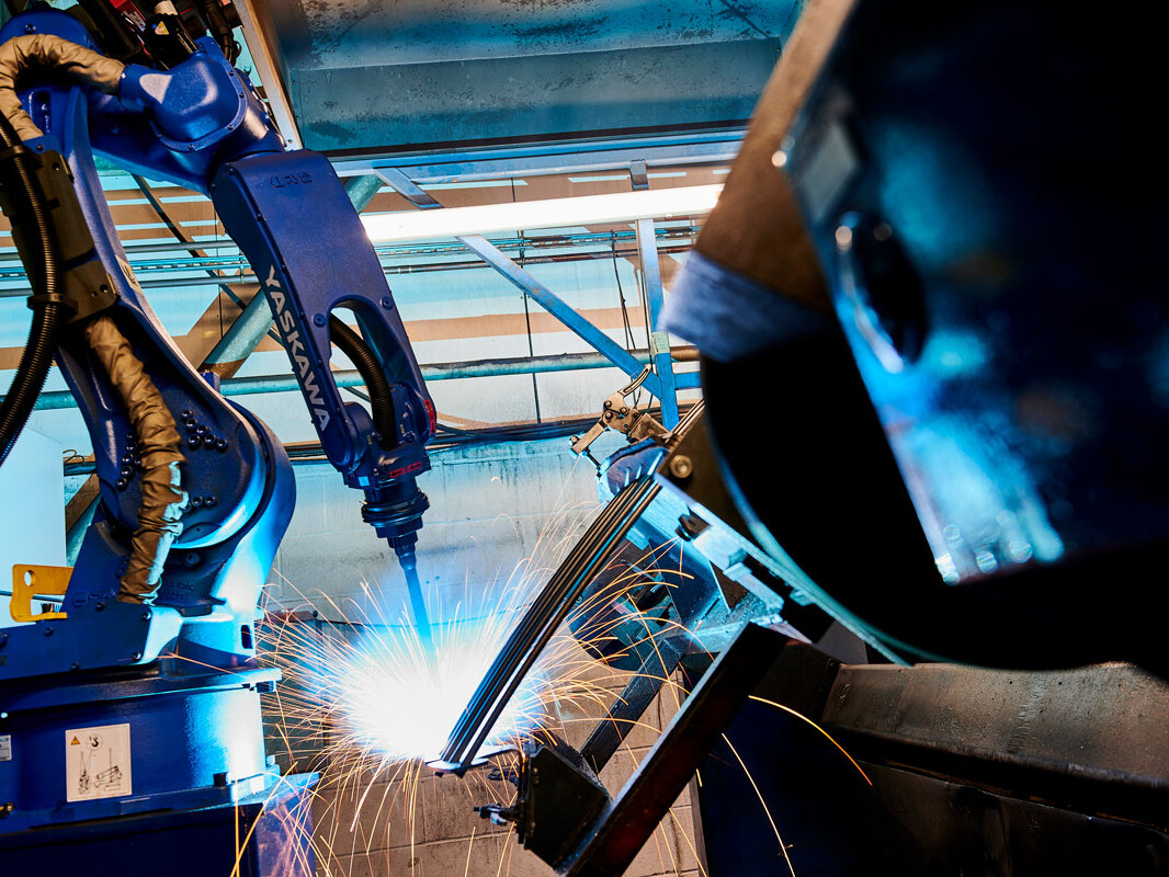
Robotic Bending
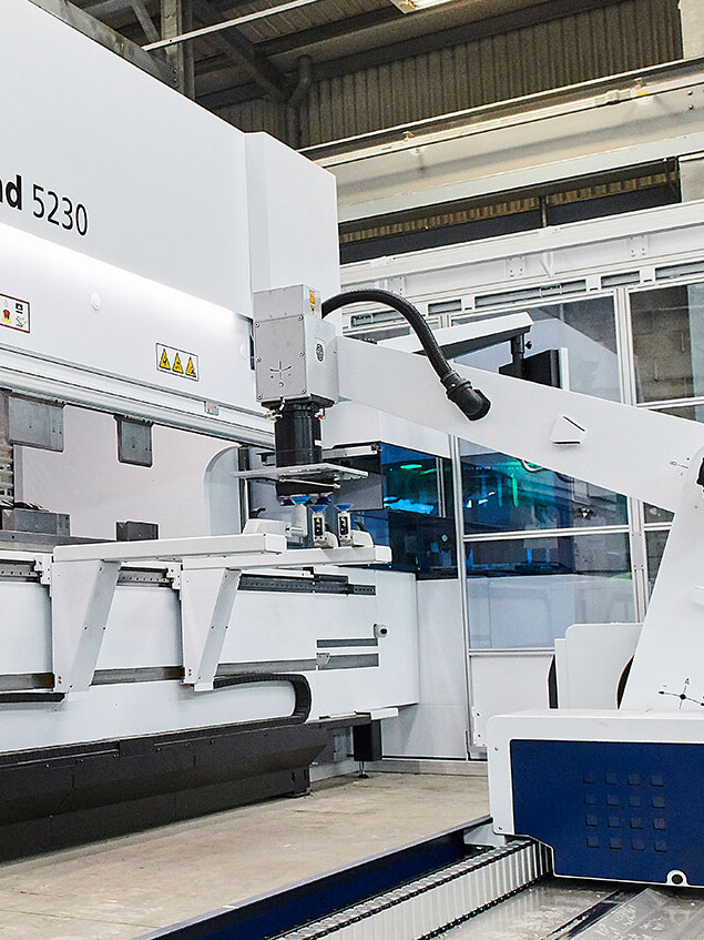
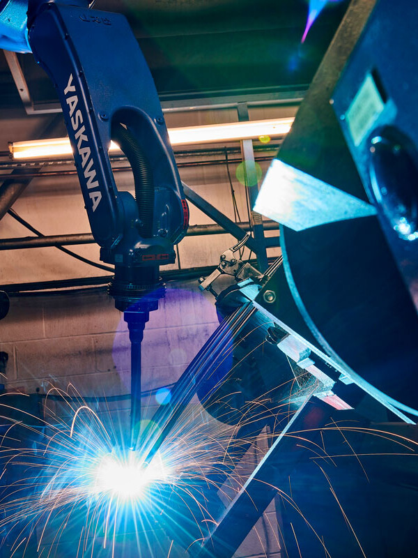
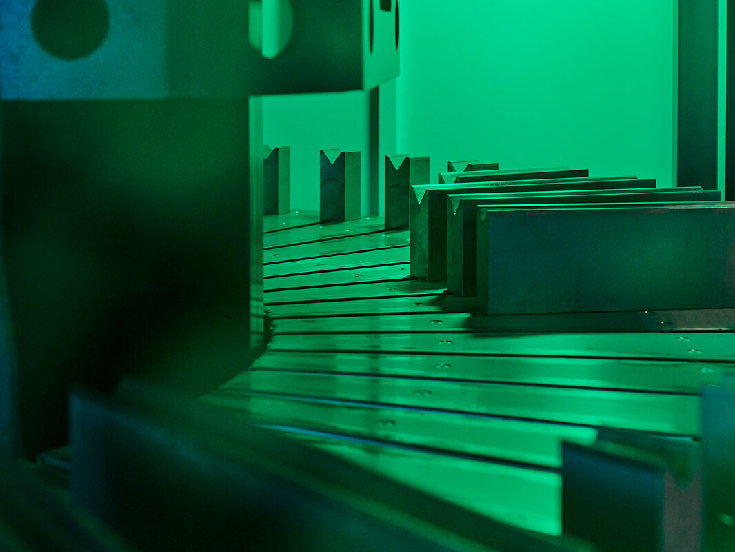
Robotic bending provides repeatability, precision and increased safety. The ability to operate ‘lights out’ allows for a fast and cost-effective metal bending, without compromising quality.
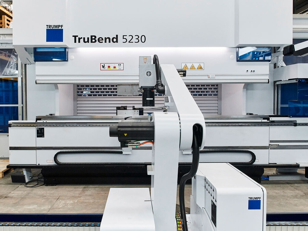
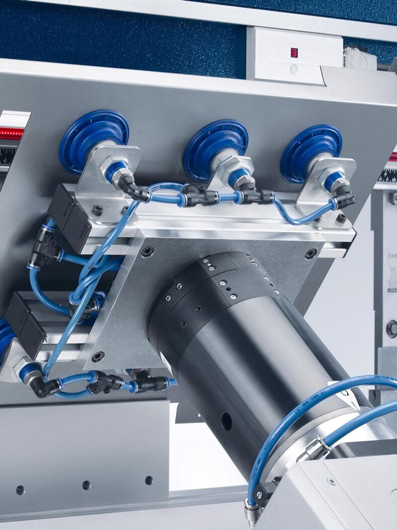
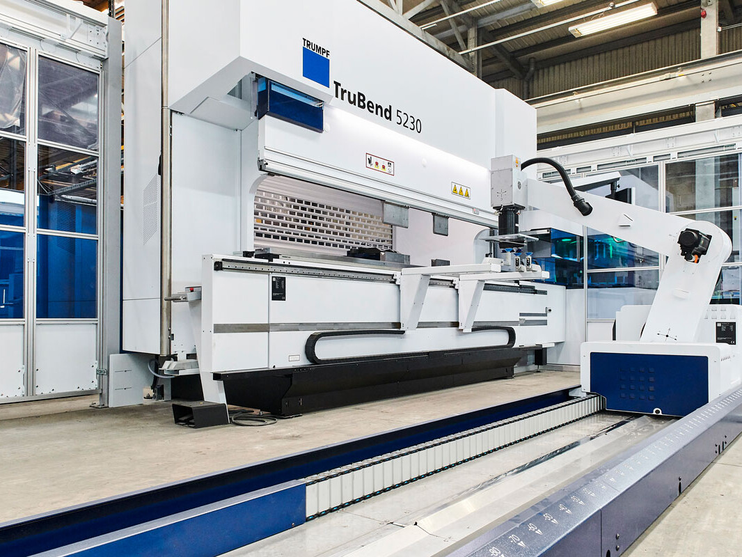
Newfield’s new TruBend Cell 5000 provides productive and flexible automation for a wide range of products, producing them to a consistently high standard. It is capable of producing parts up to 100kg with very precise angles. It is also incredibly efficient and reduces production time while maintaining reliable output and material handling.
Our robotic forming cell is comprised of a Trumpf bending cell – a TruBend 230S. It offers automated tool selection, material loading and a conveyor system for flexible storage. It enables us to perform ‘lights-out’ operations, where the machine is programmed and loaded before being left to run autonomously. Its built-in checks are verified by our engineers using a measurement system analysis (MSA) process.
Metal folding is used to create many products including pipes, enclosures, boxes and more, as sheet metal can be fashioned and reshaped in many ways such as rolling, indenting, bending and shearing.
Newfield’s quality assurance team carry out in-process checks throughout fabrication to ensure repeatable high accuracy, whilst advanced 3D measurement technology guarantees all components meet the very tight tolerances required by our customers.
Learn more about our design considerations for bending work.
More Information
Here at Newfield, we utilise a process known as ‘air bending’ that uses the minimum amount of force possible. This maximises the capability of the press brake while reducing tooling wear.
Bend Radius (Inside Bend Radius)
With air bending, the inside radius is predominantly determined by the die opening (also referred to as V-width). In order to reduce the required force, a larger V-width must be used. Generally, the minimum inside radius is equivalent to the thickness of the material. Because dies are manufactured in specific sizes, generous tolerances should be allowed – up to ± 30%.
Minimum Flange Length
It is recommended that the minimum flange length should be at least four times the material thickness. The V-width of the press brake determines how small the flanges can be. Smaller flanges than this are only possible with additional work, such as forming a larger flange and then machining it down, adding expense. Our team of design engineers will thoroughly analyse the manufacture of a part, including possible tooling, to ensure costs are minimised and the part meets all requirements.
Bend Relief
If a bend is too close to an adjacent edge, the material is likely to tear. To prevent this, the relief length should be greater than the radius of the bend. The width of the relief should also be the equivalent of the material thickness, at least. There are several advantages to a larger bend relief, including ease of component alignment, prevention of crack propagation and the reduction of setup and running costs.
Forming Near Holes
It is recommended that holes are positioned away from bends to avoid distortion. As the material is bent, the hole will deform from its original size and shape, likely preventing it from performing its intended function. Any holes located close to a bend must be created after bending as part of a secondary machining operation. To avoid the associated expenses, any holes or slot edges should be positioned so that they are clear of the die opening when the bend is formed. Generally, this means holes or slot edges must be offset around 3-4 times the material thickness from the bend line.
Bend Edge Distortion
Distortion can be created at the edge of a bend as material thickness increases and the bend radius decreases, this is part of the bending process. If this is unacceptable, then the component can be relieved.
Dimensions
Our engineering team dimensions parts in a single direction, where possible. Due to the sequential nature of the forming process, and the fact that dimensional variations are introduced by each bend, dimensioning in a single direction helps to control tolerance accumulation.
Our Engineering team not only rely on their personal expertise but also “shop-floor” knowledge, collaborating to determine the best tool selection and critically comparing this with what has been recommended by the software. This ensures that the most appropriate tool is used every time and that the parts meet the dimensional tolerances requested by the customer.
If a blank development is required, it should be marked up as ‘For Information Only’. Developments provided by third parties are often created without consideration for the actual press brake tools used during production. To guarantee the desired quality, it may be necessary to generate a blank development to suit the tooling, ensuring that the formed component matches the requirements.
Robotic Bending
Heading goes here
The process is ideally suited to both volume production and parts that are difficult to handle, heavy or complex. The aim of robotic bending is to improve accuracy through ACB technology, reducing the safety risks associated with manually forming heavier parts and reducing cost through increased productivity.
Our robotic forming cell is comprised of a Trumpf bending cell – a TruBend 230S. It offers automated tool selection, material loading and a conveyor system for flexible storage. It enables us to perform ‘lights-out’ operations, where the machine is programmed and loaded before being left to run autonomously. Its built-in checks are verified by our engineers using a measurement system analysis (MSA) process.
Metal folding is used to create many products including pipes, enclosures, boxes and more, as sheet metal can be fashioned and reshaped in many ways such as rolling, indenting, bending and shearing.
Newfield’s quality assurance team carry out in-process checks throughout fabrication to ensure repeatable high accuracy, whilst advanced 3D measurement technology guarantees all components meet the very tight tolerances required by our customers.
Get in touch to learn how Newfield Fabrications can enhance your next project.
Home
Metal Fabrication
For the last 60 years, our metal fabrications have been used around the world. Our dedication to quality has seen the business successfully expand into a number of highly demanding industries – from the automotive and MoD to nuclear and off-highway.
We are driven by the need to continuously improve. Through significant investment in staff training and leading-edge equipment, we maintain a high level of expertise and experience within the company. Newfield Fabrications remains at the forefront of the UK fabrication industry and a trusted manufacturing partner to companies worldwide.
Since 2009, Newfield have continually provided quality assemblies that have helped our company grow into a diverse range of new sectors. We have no hesitation in recommending their skilled craftsmanship and attentive customer service.
Since 2009, Newfield have continually provided quality assemblies that have helped our company grow into a diverse range of new sectors. We have no hesitation in recommending their skilled craftsmanship and attentive customer service.
Name here, Position here, Company here
Latest News
Nothing found.
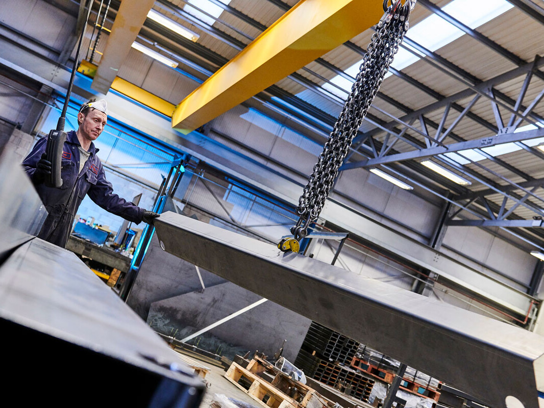
Storage & Transport
Servicing Customers Around the World
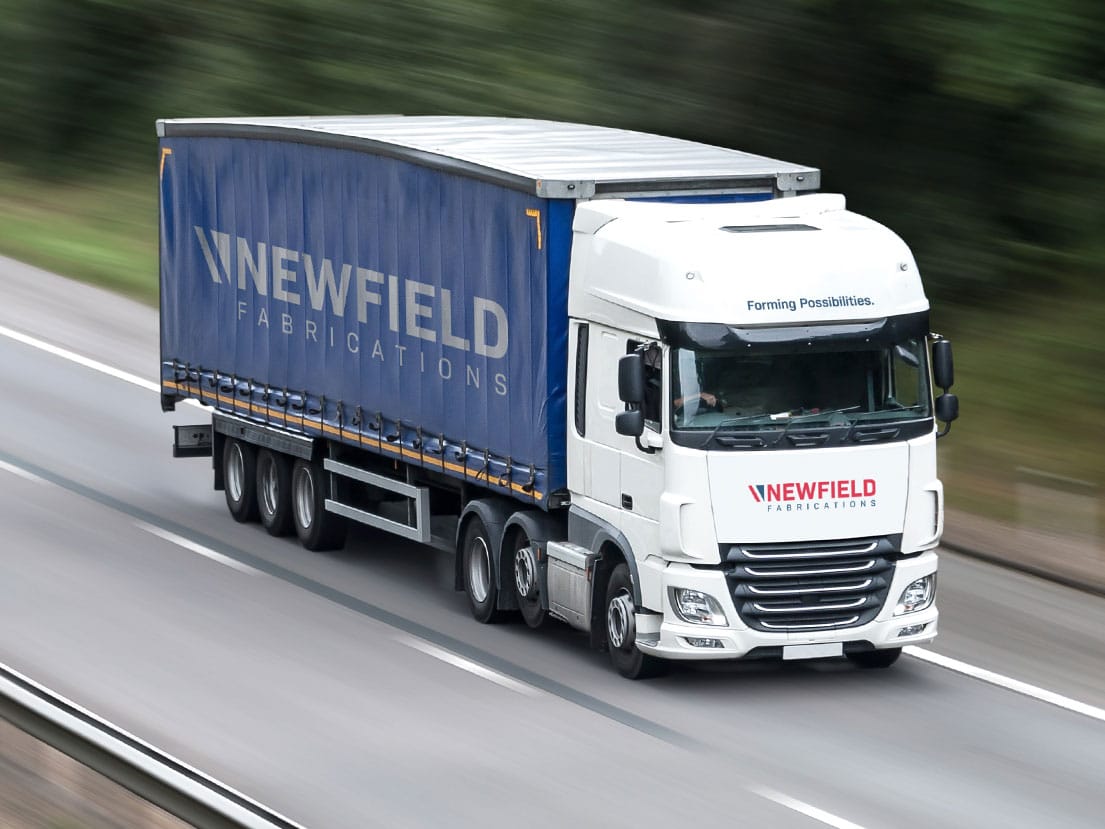
Our aim is to provide high-quality products that meet your exact specifications, precisely when you want them. Our parts are used on every continent and we have an established supply network that directly services customers in a number of countries around the world. For customers outside of the UK, we work with a specialist distribution partners. Within the UK, we operate our own delivery vehicles and can accommodate variable customer requirements. We use various incoterms, more details of which can be obtained from our sales team.
Delivery Vehicles
Newfield has a fleet of delivery vehicles with up to 26-tonne capacity. We also have access to 40-foot containers and articulated vehicles.
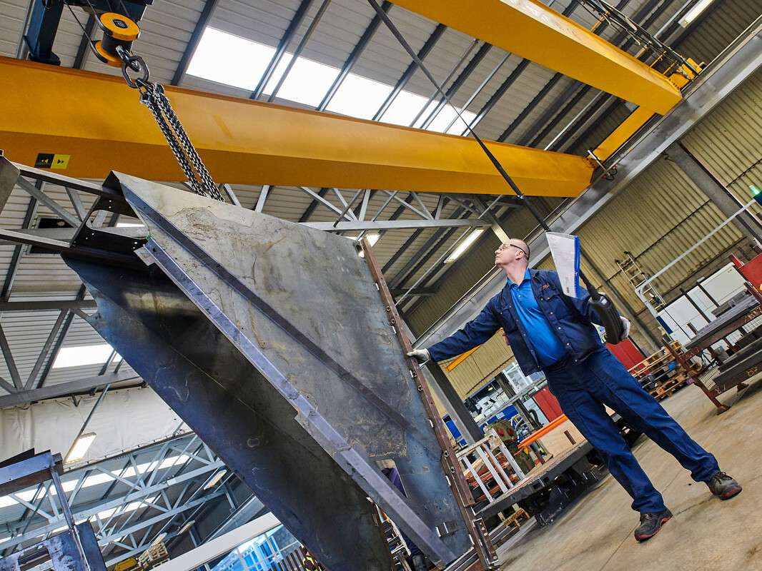
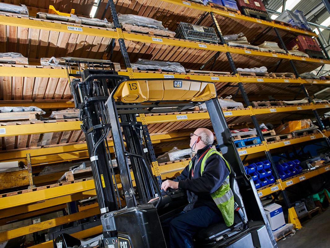
Inventory Management
Newfield utilises an Enterprise Resource Planning (ERP) system to manage and monitor stock. This can be linked through an Electronic Data Interchange (EDI) to automatically update according to customer schedules and planning additional product if required. The system is designed to ensure maximum efficiency and effectiveness by specifying locations and picking requirements. Customers are also able to arrange collections through their dedicated account managers.
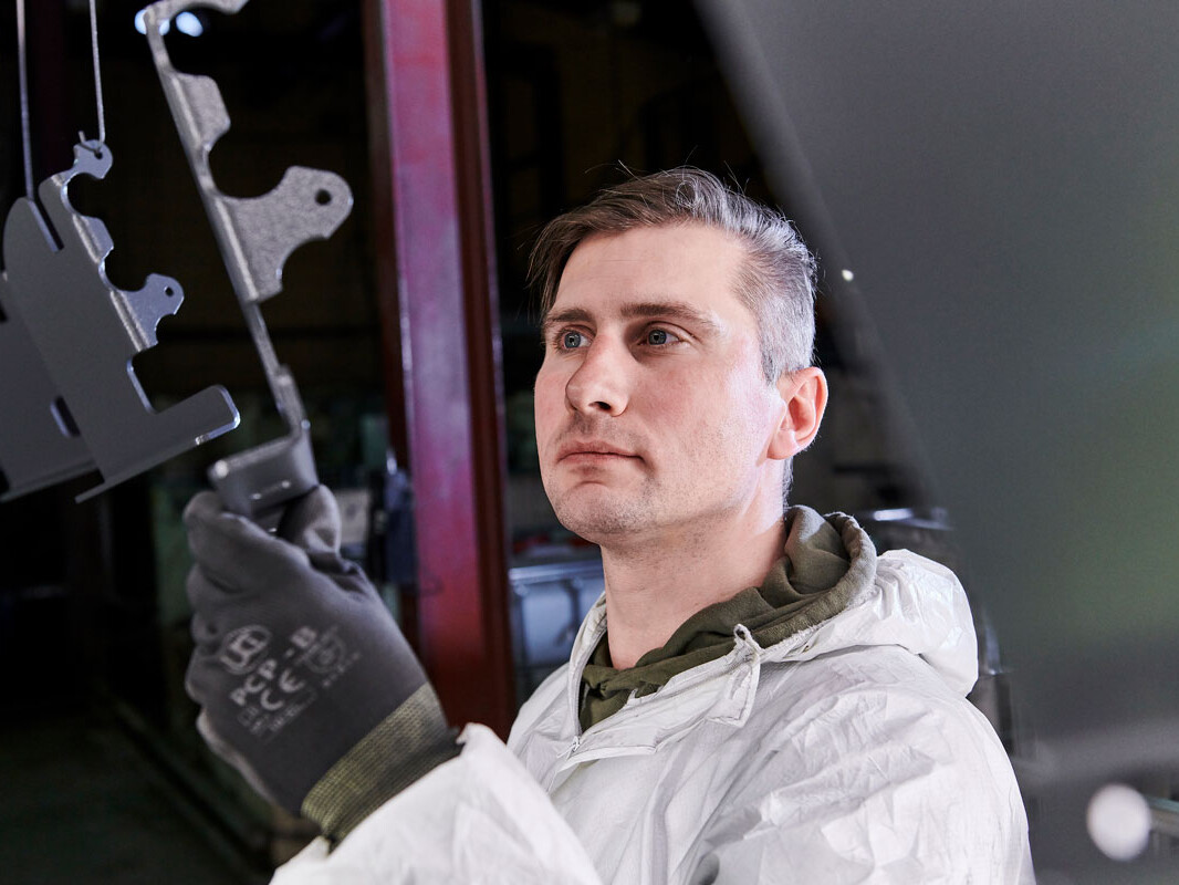
Quality Checks
Dependent on customer requirements, parts being packaged may also undergo a PDI (Pre-Dispatch Inspection). The PDI is conducted by the staff member packing the part. They will conduct various checks against specifications to ensure that the part conforms to all requirements prior to shipment.
General Assemblies
Header goes here
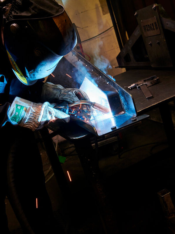
Newfield frequently carries out general assembly processes as part of its fabrication work. Here, our investment in leading-edge equipment and our team’s dedication to quality provide exceptional versatility. Our welder’s skills are continually refined, and they can perform a variety of resistance welding jobs including spot welding, projection welding and nut welding. We also offer manual assembly services for the inclusion of other fittings, such as electronics, plastic and rubber components and bunging holes.
Resistance Welding
Spot welding
Resistance spot welding (RSW) is a process in which contacting metal surface points are joined by the heat from an electric current. Workpieces are held together by two shaped copper alloy electrodes. The electrodes concentrate welding current into a small “spot” melting the metal to form a weld. At Newfield, we utilise pre-determined programmes that take into consideration material thickness, current, pressure and the duration of the process.
Projection welding
Projection welding is a modification of spot welding. In this process, the weld is localized by means of raised sections, or projections, on one or both workpieces. Heat is concentrated at the projections, which permits the welding of heavier sections or closely spaced welds. The projections can also serve as a means of positioning the workpieces. Projection welding is often used to weld studs, nuts, and other threaded machine parts to the metal plate. It is also frequently used to join crossed wires and bars. Multiple projection welds can be arranged by suitable designing and jigging.
Nut welding
Nut welding describes the projection welding process used to attach threaded nuts to a metal substrate. This is a projection weld because the nuts either have a partial or full ring projection or multiple corner edges cast a projection on the substrate. This is a very common form of welding in the automotive and appliance industries. At Newfield, we offer plate-to-plate welding as well as nut welding, stud welding and bolt welding using the several welding methods at our disposal.
Manual assembly
Many customers request that we also assemble their fabricated parts. Great care is taken by our manual assembly team to ensure high quality standards, matching those expected by our customers. Through manual assembly, we can integrate electronics, sensors, rubber and plastic components and bungholes.